NanoEmbossed shapes and fabrication methods of wire grid polarizers

a wire grid polarizer and nano-embossing technology, applied in the direction of polarising elements, instruments, optical elements, etc., can solve the problems that prior art wire grid polarizer approaches capable of scaling to large areas at low cost have not been able to achieve the optimal cross-sectional shape of metal, and achieve low cost, high transmission and contrast ratio, and high contrast ratio

Inactive Publication Date: 2010-06-03
AGOURA TECH
View PDF15 Cites 40 Cited by
  • Summary
  • Abstract
  • Description
  • Claims
  • Application Information

AI Technical Summary

Benefits of technology

[0035]Embodiments of the present invention provide wire grid polarizers with both sufficiently high transmission and contrast ratio for use in polarization recycling in LCDs capable of being produced for large areas at a low cost. Embodiments of the present invention achieve both high contrast ratio and high light transmission utilizing fabrication technology consisting of (1) creating nanoscale surface features on a thin polymer film with an embossing process that is followed by (2) an oblique deposition of metal. While there have been prior attempts to use this low cost approach for various applications, including polarization recycling in LCDs, the innovation of nanoembossed shapes with controlled angular flux of the oblique deposition results in reflective polarizers with both higher contrast and higher transmission; sufficient for the needs of the LCD industry.

Problems solved by technology

Prior attempts to achieve optimal cross-sectional line shapes are not scalable to large areas.
Prior art wire grid polarizer approaches that are capable of scaling to large areas at low cost have not been able to achieve the optimal cross-sectional shape of the metal lines that are needed to achieve high contrast ratios simultaneously with high transmission.

Method used


Image

  • NanoEmbossed shapes and fabrication methods of wire grid polarizers
  • NanoEmbossed shapes and fabrication methods of wire grid polarizers
  • NanoEmbossed shapes and fabrication methods of wire grid polarizers

Examples


Embodiment Construction

[0037]Although the following detailed description contains many specific details for the purposes of illustration, anyone of ordinary skill in the art will appreciate that many variations and alterations to the following details are within the scope of the invention. Accordingly, the exemplary embodiments of the invention described below are set forth without any loss of generality to, and without imposing limitations upon, the claimed invention.

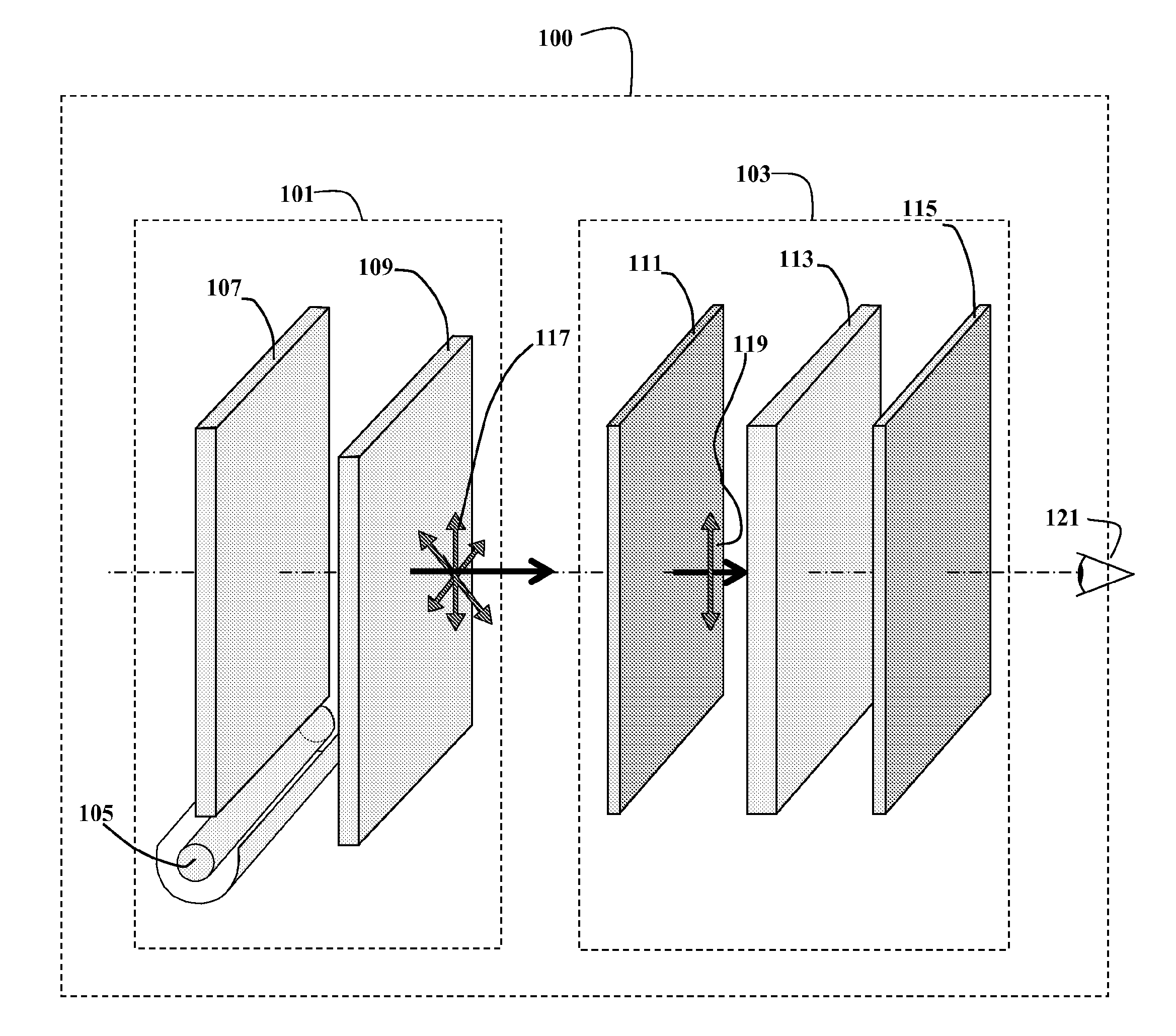
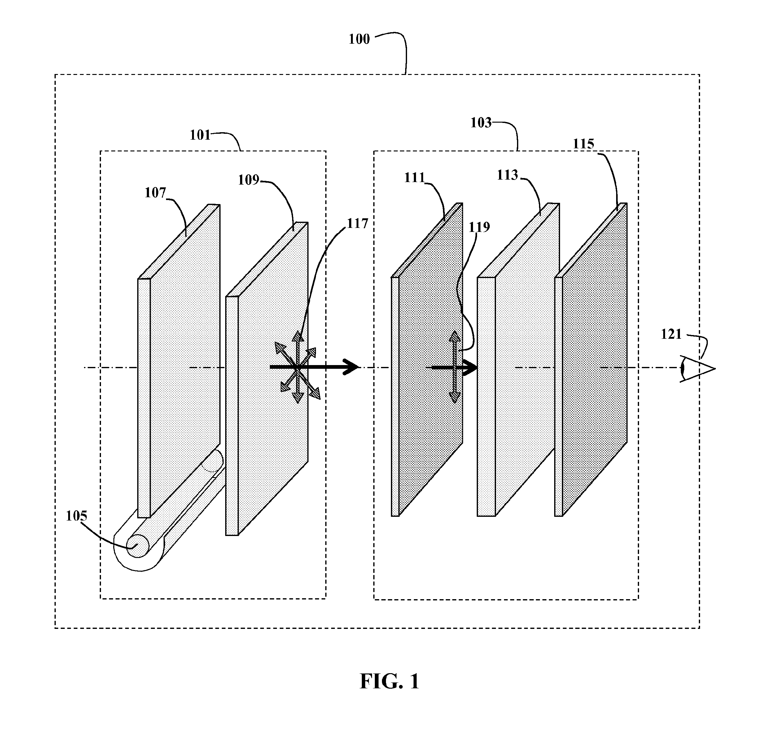
[0038]As shown in FIG. 1, in its minimal form, a liquid crystal display (LCD) 100 includes two major sub-assemblies, a backlight assembly 101 and a liquid crystal (LC) panel assembly 103. The backlight assembly 101 is minimally composed of a light source 105, a light guide 107, and a diffuser 109 to homogenize the spatial variations in the intensity of the light emanating from the backlight assembly 101. The illumination 117 provided by the backlight assembly 101 is typically unpolarized. The liquid crystal panel assembly 103 is minimally co...


PUM

PropertyMeasurementUnit
thicknessaaaaaaaaaa
heightaaaaaaaaaa
thicknessaaaaaaaaaa

Abstract

A wire grid polarizer may be formed by embossing a substrate surface with a mold having a plurality of grooves to form raised ridges; and depositing a metal line profile onto the ridges through one or more baffles oriented at an oblique angle to the normal of the substrate. The metal line profile is characterized by a cross-sectional width that tapers such that the metal line profile is wider proximate a vertex of the ridges than proximate a base of the ridges. A wire grid polarizer may comprise a substrate with a plurality of raised ridges and a plurality of metal lines on the raised ridges. The metal lines are characterized by cross-sectional metal line profiles having triangular shapes with a tip down configuration. Such a wire grid polarizer may be used in a liquid crystal display.

Description

CLAIM OF PRIORITY[0001]This application clams the benefit of priority of U.S. Provisional Patent Application No. 60 / 953,668, filed Aug. 2, 2008, the entire contents of which are incorporated herein by reference.[0002]This application clams the benefit of priority of U.S. Provisional Patent Application No. 60 / 953,652, filed Aug. 2, 2008, the entire contents of which are incorporated herein by reference.[0003]This application clams the benefit of priority of U.S. Provisional Patent Application No. 60 / 953,658, filed Aug. 2, 2008, the entire contents of which are incorporated herein by reference.[0004]This application clams the benefit of priority of U.S. Provisional Patent Application No. 60 / 953,671, filed Aug. 2, 2008, the entire contents of which are incorporated herein by reference.CROSS-REFERENCE TO RELATED APPLICATIONS[0005]This application is related to International Patent Application PCT ______, (Attorney Docket Number AGT-005 / PCT, to Michael J. Little, entitled “A WIRE GRID PO...

Claims


Application Information

Patent Timeline
Patent Type & Authority Applications(United States)
IPC IPC(8): G02F1/1335G02B5/30B05D5/06
CPCC23C14/02C23C14/225C23C14/205C23C14/042
Inventor JOHNS, CHADEGAN, ERIKLITTLE, MICHAEL J.
Owner AGOURA TECH
Why Eureka
Try Eureka