Method and System for Retrieving Diagnostic Information

Active Publication Date: 2010-06-03
MITCHELL REPAIR INFORMATION
View PDF22 Cites 109 Cited by
  • Summary
  • Abstract
  • Description
  • Claims
  • Application Information

AI Technical Summary

Benefits of technology

[0010]In light of the above, a method for quickly and automatically retrieving only relevant di

Problems solved by technology

Though technicians normally see this activity as a part of their job, it can be a time consuming process.
The time elem

Method used


Image

  • Method and System for Retrieving Diagnostic Information
  • Method and System for Retrieving Diagnostic Information
  • Method and System for Retrieving Diagnostic Information

Examples


Embodiment Construction

I. Overview of the Diagnostic System Architecture

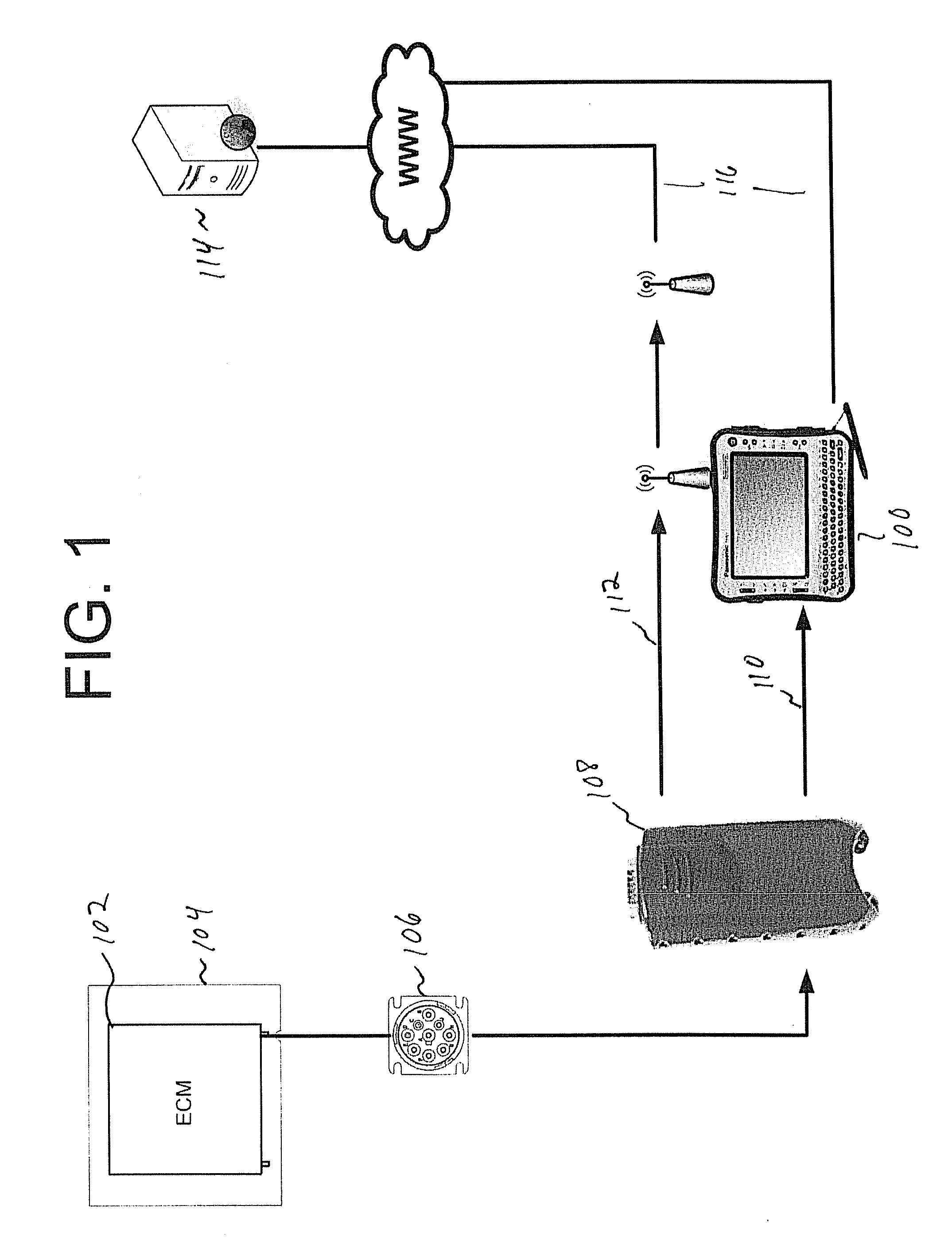
[0030]FIG. 1 is a block diagram of an exemplary system using a diagnostic information portal to provide only relevant diagnostic information to a requesting diagnostic tool. As illustrated, a diagnostic tool 100 interfaces with an Engine Control Module (ECM) 102 or other similar circuit contained within a vehicle 104 via a vehicle interface port 106 and PC-to-vehicle interface 108. Although an ECM is a standardized control module and is illustrated in FIG. 1, any type of electronic error reporting and storage device could be used. The motor vehicle 104 may be a passenger car, a light duty truck, a tractor-trailer truck, or any other type of motor vehicle or general electro-mechanical system. Additionally, the disclosure of a motor vehicle 104 in FIG. 1 is exemplary in nature only, and equipment under diagnosis could be any electro-mechanical device. As set forth in FIG. 1, the diagnostic tool 100 may communicate with the PC-to-vehicle...


PUM


Abstract

A system, method, and apparatus for retrieving trouble codes from an equipment under diagnosis and retrieving only relevant diagnostic information relative to the returned codes from one or more remote diagnostic libraries. An electronic diagnostic library contains diagnostic vehicle information tagged with trouble code identification ID's at a first location, and a diagnostic tool at a second location requests only relevant diagnostic information from the electronic library that is tagged with trouble code identification ID's corresponding to the retrieved trouble codes and information identifying the equipment under diagnosis. The diagnostic tool receives the specific diagnostic vehicle information at the first location and may store the specific vehicle information locally prior to displaying an index to the information to a repair technician.

Description

BACKGROUND[0001]1. Field of the Application[0002]This application relates generally to test and diagnostic systems for equipment under diagnosis, particularly motor vehicles. More specifically, the application relates to an automated process for retrieving diagnostic information relative to returned trouble codes from one or more equipment components under diagnosis. While the application is described in the context of a motor vehicle diagnostic system and method, the principles of the present application are equally applicable for any testing and diagnostic systems, including non-motor vehicle equipment, as long as the equipment under diagnosis stores trouble codes relative to a past or current error condition.[0003]2. Description of the Related Art[0004]Motor vehicles are becoming highly computerized products. In recent years, for example, the control of internal combustion engines has branched away from traditional mechanical linkages and analog approaches to electronic or microp...

Claims


Application Information

Patent Timeline
IPC IPC(8): G06F11/07
CPCG05B23/0272G06F16/24573
Inventor COSTANTINO, DAVID
Owner MITCHELL REPAIR INFORMATION
Why Eureka
Try Eureka