Valve system

a valve system and valve body technology, applied in the field of valve systems, can solve the problems of difficult system maintenance, strain on connectors, housings, other system components, and disadvantages of constant fluid pressure on the system, and achieve the effect of easy maintenance and less cos

Inactive Publication Date: 2010-06-10
ACCESS BUSINESS GRP INT LLC
View PDF69 Cites 21 Cited by
  • Summary
  • Abstract
  • Description
  • Claims
  • Application Information

AI Technical Summary

Benefits of technology

[0007]In another embodiment, the valve system includes a second actuator connected to the automatic shutoff. The second actuator is capable of moving the moveable element to the closed position regardless of the pressure differential on the automatic shutoff. In this way, the second actuator may act independently from the ordinary actuation of the automatic shutoff to force the valve system partially or completely closed. The second actuator may be manual or automatically operated, and in one embodiment the second actuator may be connected to one or more sensors that signal the second actuator to close upon the occurrence of a particular event. The second actuator may be in the form of a threaded shaft extending into the valve system housing. When the shaft is driven into the valve system, it causes the moveable element to move at least partially toward the closed position, which restricts or completely prevent flow through the valve system.
[0008]The valve system of the present invention provides a reliable device that can be inserted in-line with a water treatment system to allow use of a standard single-line outlet with the water treatment system while allowing the system to rest at low pressure. The valve system is also capable of providing pressure protection for water treatment systems and a wide variety of other fluid dispensing systems by preventing fluid flow to these devices when the dispensing outlet is closed. Such devices may include hot water heaters, beverage vending machines, drinking fountains, water softeners, refrigerator ice / water dispensers, dairy processors, food processing systems, air compressors, and hydraulic systems. The valve system enables easy maintenance of these devices by removing pressure from the device (and removing fluid flow to the device) when the dispensing outlet is turned off. Additionally, the internal components of any dispensing devices using the valve system may be lighter, smaller, and thus less expensive as they no longer have to withstand constant high pressure.
[0009]In the embodiment including a second actuator, the valve system can provide pressure protection for a variety of fluid flow devices along with additional functionality, such as system shutoff upon leak detection and flow regulation. This embodiment can be useful in many of the fluid flow applications noted above, for instance, by configuring the second actuator to shut off the fluid flow to the devices upon the detection of an undesirable event, such as a leak in the system. It can also be useful in regulating the amount of fluid that flows to a particular device, such as a gas gill, dish washer or washing machine.

Problems solved by technology

Unfortunately, there are only a limited number of styles and options for three-line faucets, creating a need for a system that enables the use of a standard single-line faucet for dispensing treated water from a water treatment system while limiting the pressure on the system.
In addition to water treatment systems, a variety of other fluid flow systems, such as hot water heaters, beverage vending machines, and hydraulic and pneumatic cylinder systems suffer from disadvantages associated with the constant fluid pressure on the system.
The high fluid pressure experienced by many of these systems places a strain on the connectors, housings, and other system components, and can make it difficult to conduct maintenance on the system without shutting off the fluid source at a separate, and sometimes remote, location.
Even greater problems are caused when this high pressure causes the water treatment system or another type of fluid flow system to fail, causing the fluid to leak continuously until it is detected and can be shut off at its source.

Method used


Image

  • Valve system
  • Valve system
  • Valve system

Examples


Embodiment Construction

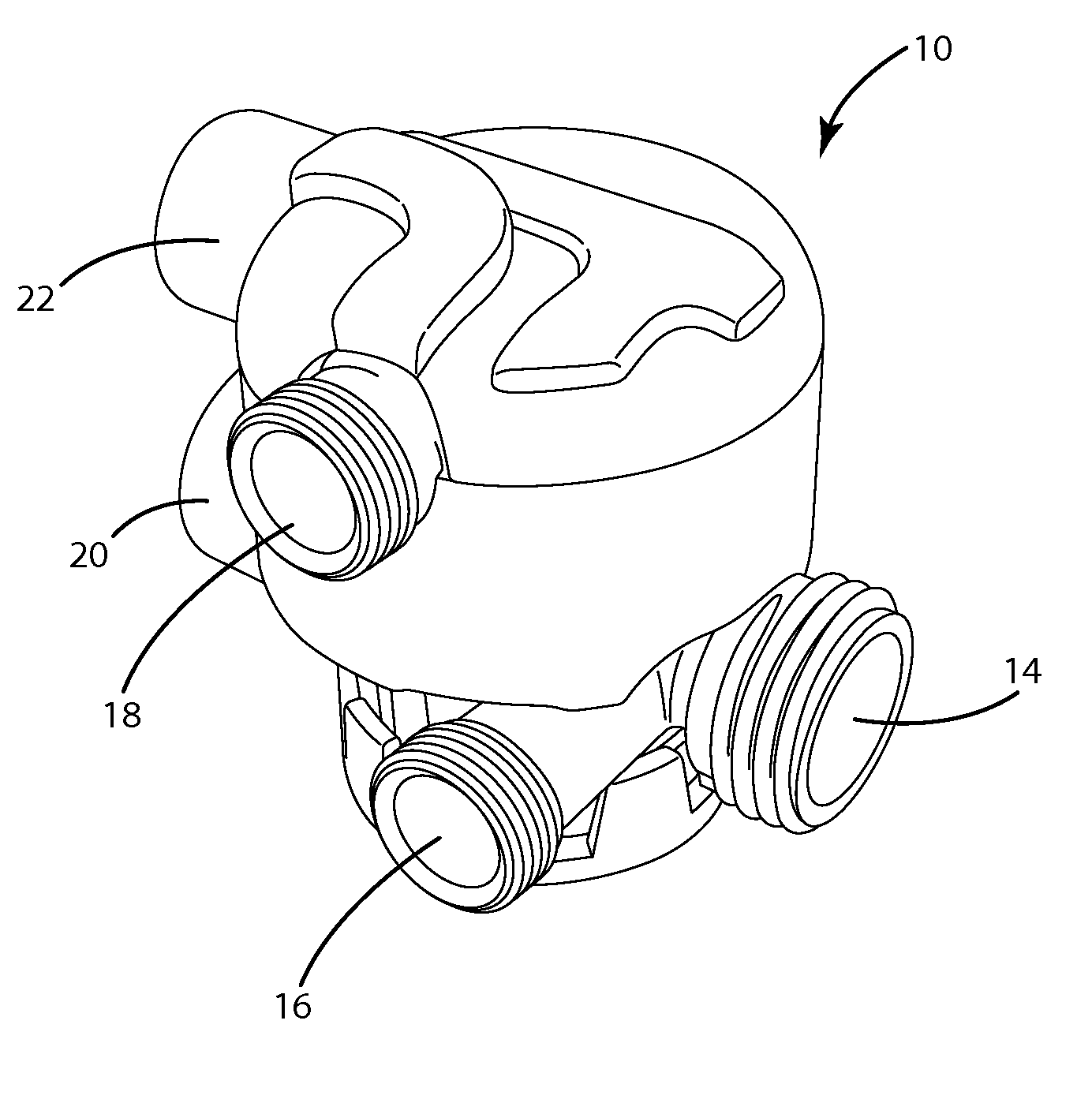
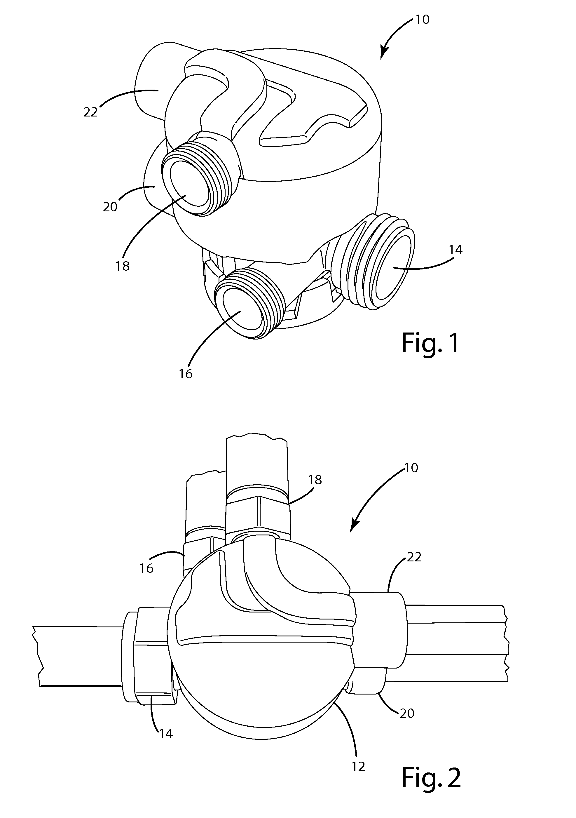
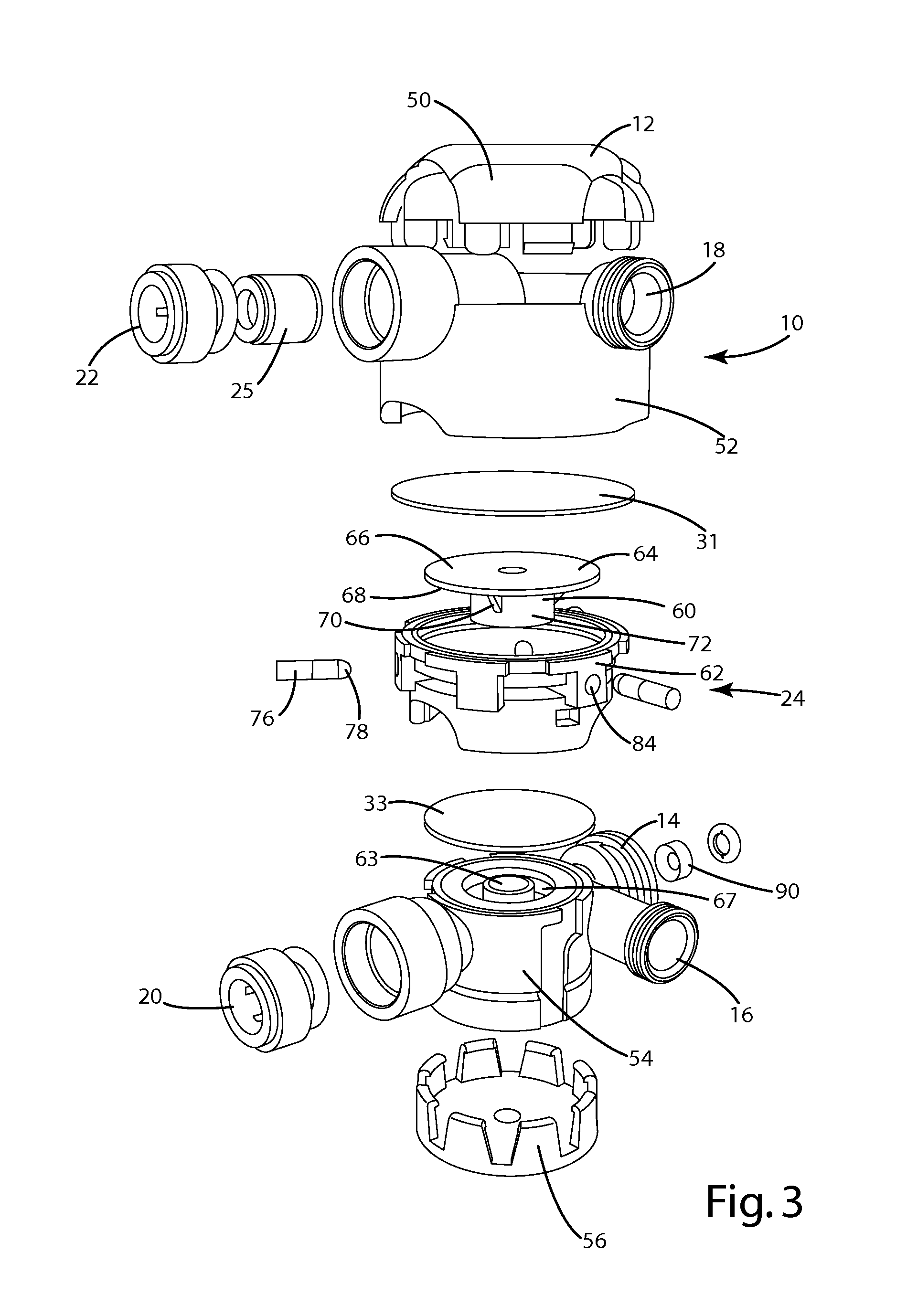
[0027]A valve system according to one embodiment of the present invention is shown in FIGS. 1-3 and generally designated 10. The valve system 10 is configured to be used in a variety of applications. In one application, the valve system 10 enables use of a standard single line faucet with a water treatment system. In another application, the valve system 10 protects a fluid dispensing device, such as a water treatment system, a hot water tank, or a beverage vending machine from unwanted pressure.

[0028]The valve system 10 typically includes a plurality of ports for connecting the valve system 10 to the supply water, the faucet, and a down stream device, such as a water treatment system 11. As illustrated, the valve system 10 includes a housing 12 that has a supply water inlet port 14, an untreated water outlet port 16, a treated water outlet port 18, a water treatment system outlet port 20 and a water treatment system inlet port 22. An automatic shutoff valve 24 is positioned within ...


PUM


Abstract

A valve system enables use of a standard single line faucet with a water treatment system, protects water treatment systems and other fluid flow devices from unnecessary fluid pressure, and regulates or prevents fluid flow to a dispenser or outlet in response to a particular event, such as a leak. The valve system includes a housing having ports for: (1) receiving a supply fluid, (2) supplying the fluid to a device, such as a water treatment system, (3) receiving the fluid from the device and (4) supplying fluid to a dispenser. The valve system also includes an automatic shutoff device within the housing that prevents water from flowing into the housing and the water treatment system when the dispensing outlet is closed and that allows water to flow through the housing and into the water treatment system when the outlet is open. The valve system may also include a second actuator connected to the automatic shutoff that is capable of moving the automatic shutoff to a partially or fully closed position.

Description

BACKGROUND OF THE INVENTION[0001]The present invention is directed to valve systems, and more particularly to a valve system for regulating flow and pressure in water treatment systems and other fluid flow systems.[0002]Water treatment systems are well known for providing filtered, treated water. These systems typically include an inlet for receiving untreated water from a supply line, one or more filters for treating the water, and an outlet for the treated water. The treated water outlet may be connected to a outlet, such as a faucet, that can be opened (i.e. “turned on”) to dispense the treated water. Currently, many water treatment systems can only be used with a “three-line” faucet that includes a first line for untreated water supply to the water treatment system, a second line that receives the treated water from the system, and a third line that receives untreated water from a supply source. This configuration serves to limit pressure on the water treatment system when ‘wait...

Claims


Application Information

Patent Timeline
Patent Type & Authority Applications(United States)
IPC IPC(8): G05D16/20F16K15/00F16K11/00
CPCE03C1/04F16K15/18F16K7/12E03C2201/40Y10T137/0396Y10T137/7904Y10T137/2496Y10T137/7837Y10T137/87153Y10T137/7782Y10T137/87249Y10T137/87048Y10T137/0379
Inventor LAUTZENHEISER, TERRY L.GODFREY, DAVID O.MILES, MICHAEL E.MORK, STEVE O.BYLSMA, RICHARD B.
Owner ACCESS BUSINESS GRP INT LLC
Why Eureka
Try Eureka