Apparatus and method for separating and isolating components of a biological fluid

a biological fluid and apparatus technology, applied in the direction of centrifugal force sediment separation, other medical devices, intravenous devices, etc., can solve the problems of inability to maintain a seal, inconvenient extraction method, and inability to maintain the precise inner diameter

Active Publication Date: 2010-06-10
THERMOGENESIS HLDG INC
View PDF96 Cites 147 Cited by
  • Summary
  • Abstract
  • Description
  • Claims
  • Application Information

AI Technical Summary

Benefits of technology

[0014]Accordingly, and in one aspect, an embodiment of the invention ameliorates or overcomes one or more of the significant shortcomings of the know prior art by providing a separation and isolation device comprising a float assembly slideably enveloped in an enclosure containing biological fluid for promoting fluid flow into and automatic self sealing of a chamber of the funnel float for isolating at least one component or fraction of a biological fluid being processed.

Problems solved by technology

A major problem with that device was the inability to maintain a seal because it is costly to maintain the precise inner diameter of the test tube when mass produced.
This method of extraction necessarily is inefficient as a means of cell recovery as the intruding needle necessarily relocates the target cells above and below the through bore as it is inserted.
Hence, these known mechanical devices are generally capable of separating biological fluids into component parts or fractions; however, these devices are not very precise thereby resulting in inefficient separation of the biological fluid into component parts or fractions because of the substantial comingling of the separated fractions.
Additionally, these known mechanical devices fail to provide a simple or efficient method to extract a fraction other than the top fraction of the sample leading to low recoveries, especially of the clinically important buffy coat fraction.
Accordingly, this device relies on the imprecise longitudinal compression and decompression of the tube wall in order to control the flow path between fractions and fails to contain the separated fractions until after centrifugation stops and the tube wall returns to its original dimensions.
Hence, this recently patented device still fails to alleviate the problem of inefficient separation of the biological fluid into component parts or fractions and the comingling of the separated fractions.
This embodiment describes only one centrifugation spin, and fails to alleviate the problem of inefficient separation of the biological fluid into component parts or fractions and the comingling of the separated fractions.
Moreover, the device relies on the imprecise longitudinal compression and decompression of the tube wall in order to control the flow path between fractions and fails to contain the separated fractions until centrifugation stops and decompression of the tube wall is concluded.
Another problem associated with both embodiments of Leach, et al. is that the collection face, trough, or sump of the buoy must be shallow to be at a desired density level of the target buffy coat fraction and to preclude even further accumulation of reds cells with the target white cells and platelets to be extracted.
Thus, this shallow trough results in having the target white blood cells and platelets, come to rest on the entire large surface area of the first piston on which the white blood cells and platelets tend to stick, which reduces the efficiency of the final collection step.
A further problem associated with both embodiments of Leach, et al. is the time consuming and laborious process of fitting and interconnecting multiple parts to the device in order to perform the extraction process.
In general, current processes for separating and extracting fractions out of biological fluids require multiple steps that are both laborious and time consuming and that result in poor recoveries of the target white cells and platelets.
Process simplification also has a direct correlation to process reproducibility that is also a problem with the known prior art.
Hence, the known prior art is problematic in a number of areas which include a deficiency in the recovery efficiency of cells of interest (target cells), in the selectivity of separation for reducing contamination or non-target cells from the target cell population, and in the multiple step, laborious, and time consuming extraction process.

Method used


Image

  • Apparatus and method for separating and isolating components of a biological fluid
  • Apparatus and method for separating and isolating components of a biological fluid
  • Apparatus and method for separating and isolating components of a biological fluid

Examples


Embodiment Construction

[0066]Considering the drawings, wherein like reference numerals denote like parts throughout the various drawing figures, reference numeral 10 is directed to an embodiment of a device for separating and isolating components of a biological fluid and reference numeral 310 is directed to another embodiment of the device for separating and isolating components of a biological fluid.

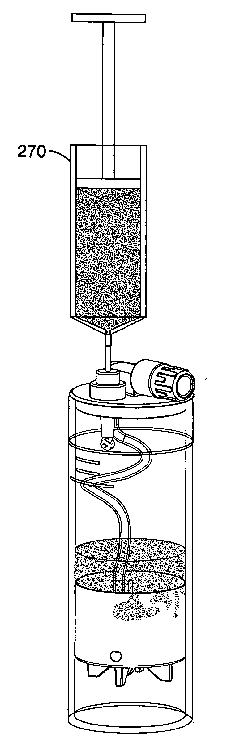
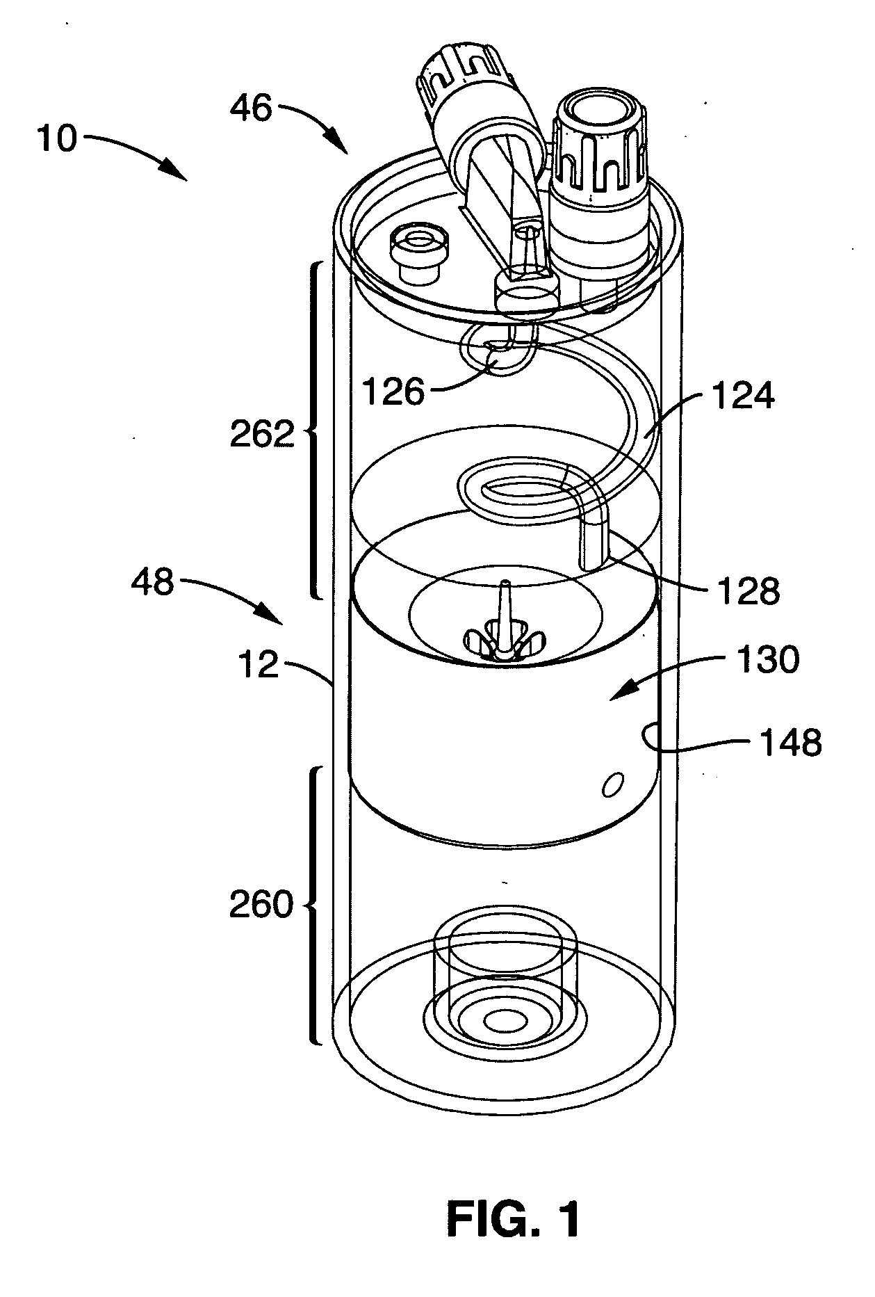
[0067]Referring now to FIG. 1, and in one embodiment, the device 10 is comprised of a main centrifuge tube or container 12, a tube cap assembly 46 for selectively closing the container 12 for defining an enclosure 48 for receiving and containing a biological fluid having multiple components, a float assembly 130 partitioning the enclosure into a first or lower volume zone 260 below the float assembly 130 and a second or upper volume zone 262 above the float assembly 130, and a flexible tube 124 operatively coupled between the float assembly 130 and the tube cap assembly 46 for traveling up or down with the f...


PUM

PropertyMeasurementUnit
densityaaaaaaaaaa
densityaaaaaaaaaa
densityaaaaaaaaaa

Abstract

A device for separating and isolating components of a biological fluid comprising a container for containing the fluid to be processed, a tube cap assembly for closing the container while providing filling and extraction communication therewith, a float assembly disposed within the container for funneling and controlling biological fluid flow into an inverted domed shaped isolation chamber within the float and controlling the biological fluid flow out of the isolation chamber for effecting an encapsulation or a sealed isolation of at least one component or fraction of the biological fluid flow within the isolation chamber during a centrifugation process. The device further comprising a flexible tube for connecting an extraction passageway disposed within the float assembly and an extraction valve of the tube cap assembly for allowing extraction of at least the one component or fraction encapsulated or isolated within the chamber.

Description

FIELD OF THE INVENTION[0001]This invention relates generally to devices and methods for separating biological fluids into components having different densities and, in particular, to an apparatus and method for receiving a biological fluid sample, separating components of the biological fluid sample while isolating at least one target component from non-target components of the biological fluid sample based upon fluid component density differences, and extracting at least one isolated target component in preparation for at least one diagnostic or therapeutic application. This invention is particularly useful in the centrifugal separation of blood and bone marrow into components.BACKGROUND OF THE INVENTION[0002]It is known to separate biological fluids, such as aspirated bone marrow or peripheral blood, into their component parts, fractions, phases, or constituent layers by centrifugation. It is also known to provide mechanical devices comprised of a tube which houses a solid separat...

Claims


Application Information

Patent Timeline
Patent Type & Authority Applications(United States)
IPC IPC(8): B01D21/34B01D21/26
CPCA61M1/029B01D21/26A61M2202/0464A61M2202/10B01L3/50215B01L2300/048B01L2300/049B01L2300/0681B01L2400/0605B01L2400/0611G01N2035/00495B01D21/307B01D21/262B01D2221/10B01D21/34A61M2202/0413
Inventor CHAPMAN, JOHN R.KUMAR, VIJAYCINQUINI, BRIAN K.KINGSLEY, PHILIP D.
Owner THERMOGENESIS HLDG INC
Why Eureka
Try Eureka