Hardened current mode logic (CML) voter circuit, system and method

a current mode and voter circuit technology, applied in logic circuits, pulse techniques, reliability increasing modifications, etc., can solve problems such as logic errors and improper operation of electronic circuits

Active Publication Date: 2010-06-10
BAE SYST INFORMATION & ELECTRONICS SYST INTERGRATION INC
View PDF8 Cites 10 Cited by
  • Summary
  • Abstract
  • Description
  • Claims
  • Application Information

AI Technical Summary

Problems solved by technology

In outer space, for example, high-energy protons or heavy ions (cosmic rays) are types of radiation that can cause logic errors when impacting integrated circuits.
A single event upset is a radiation-induced error in the logic state of a signal within the integrated circuit.
Such an error can result from the collision between a high-energy proton or a heavy ion and the semiconductor material that forms the integrated circuit.
Such invalid logic conditions may, of course, result in improper operation of electronic circuitry (not shown) of which the buffer 100 is a part.

Method used


Image

  • Hardened current mode logic (CML) voter circuit, system and method
  • Hardened current mode logic (CML) voter circuit, system and method
  • Hardened current mode logic (CML) voter circuit, system and method

Examples


Embodiment Construction

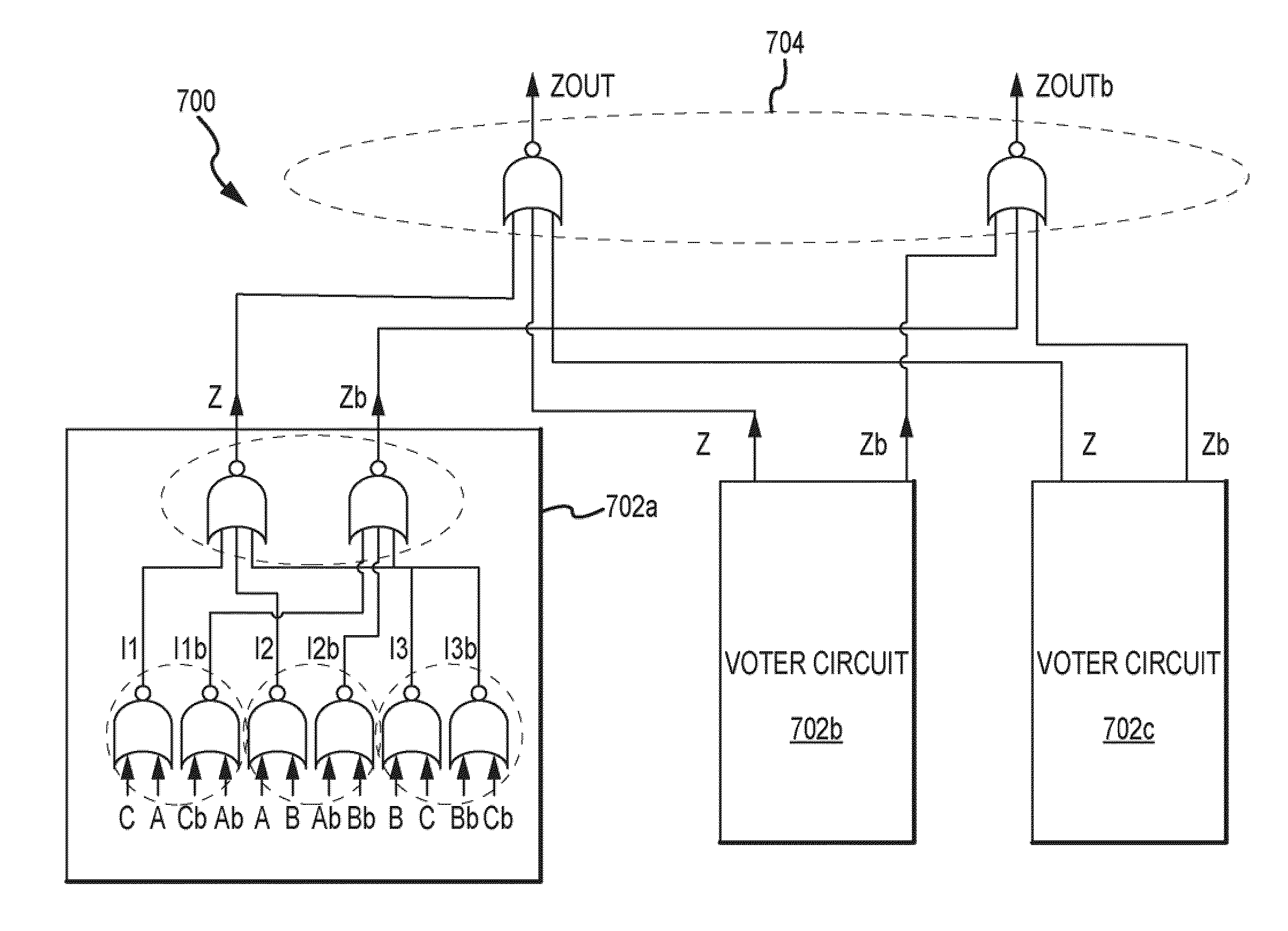
[0026]FIG. 6 is a schematic of a hardened current mode logic voter circuit 600 including three two-input split NOR gates 602a-c that apply their outputs to a three-input split NOR gate 604 according to one embodiment of the present invention. The voter circuit 600 is utilized electronic circuitry and systems in place of the voter 400 and FIG. 4. In operation, the voter circuit 600 enables the utilization of triple mode redundancy in current mode logic circuitry without propagating any errors that may arise due to single event upsets, as will be explained in more detail below.

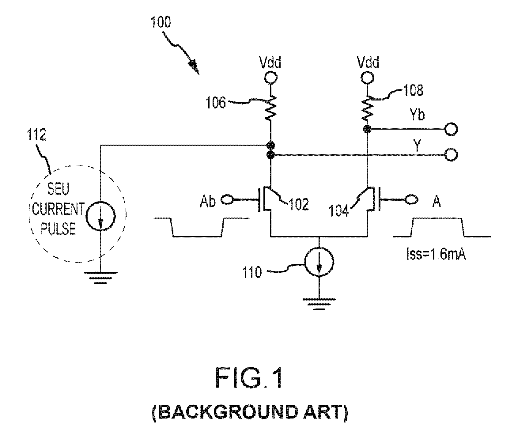
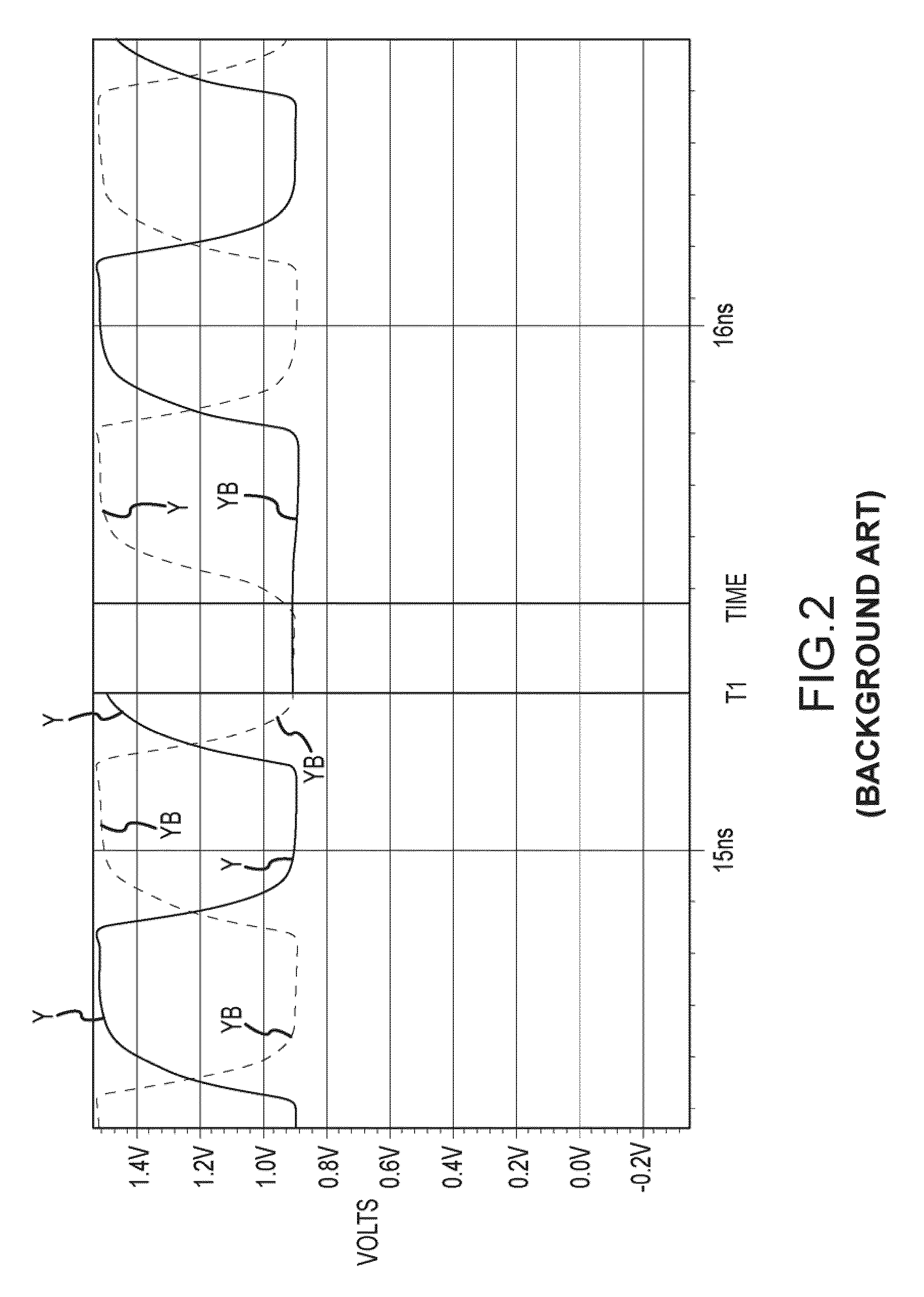
[0027]In the following description, certain details are set forth in conjunction with the described embodiments of the present invention to provide a sufficient understanding of the invention. One skilled in the art will appreciate, however, that the invention may be practiced without these particular details. Furthermore, one skilled in the art will appreciate that the example embodiments described below do not...


PUM


Abstract

A current mode logic voter circuit includes three two-input split NOR gates. Each two-input split NOR gate receives a corresponding pair of input signals and generates a pair of first output signals responsive to the input signals. A three input split NOR gate is coupled to the two-input split NOR gates to receive the first output signals and generates a second pair of output signals responsive to the first output signals from the two-input split NOR gates. The two and three-input split NOR gates can be formed from current mode logic buffer circuits, and in one embodiment in the three-input split NOR gate the buffer circuits are hardened.

Description

PRIORITY CLAIM[0001]The present application is a national phase application filed pursuant to 35 USC §371 of International Patent Application Serial No. PCT / US2008 / 086291, filed 10 Dec. 2008; which claims the benefit of U.S. Provisional Patent Application Ser. No. 61 / 007,340, filed 10 Dec. 2007, now expired; all of the foregoing applications are incorporated herein by reference in their entireties.STATEMENT OF GOVERNMENT INTEREST[0002]The invention was made with United States Government support under Contract No. DTRA01-03-D-0007 / 0007, awarded by the Department of Defense. The United States Government has certain rights in this invention.TECHNICAL FIELD[0003]Embodiments of the present invention relate generally to electronic circuitry including current mode logic that operates in environments where radiation-induced logic errors may occur.BACKGROUND OF THE INVENTION[0004]Integrated circuits are operated in environments where radiation-induced logic errors may occur, such as in outer...

Claims


Application Information

Patent Timeline
Patent Type & Authority Applications(United States)
IPC IPC(8): H03K19/003H03K19/094
CPCH03K19/23
Inventor WOOD, NEILREA, DAVIDLI, BIN
Owner BAE SYST INFORMATION & ELECTRONICS SYST INTERGRATION INC
Why Eureka
Try Eureka