Shift register

a technology of shift register and layout area, applied in the field of shift register, can solve the problems of increasing layout area and power consumption of clock interconnection, and achieve the effects of preventing erroneous operation of shift register, low power consumption, and low power consumption

Active Publication Date: 2010-06-10
SHARP KK
View PDF12 Cites 36 Cited by
  • Summary
  • Abstract
  • Description
  • Claims
  • Application Information

AI Technical Summary

Benefits of technology

[0018]According to the first aspect of the present invention, it is possible to generate the reset signal at the on-level without flow of a through current by use of the two-phase clock signals whose on-level periods do not overlap with each other, and to apply the off-voltage to the control terminal of the output control transistor by use of the reset signal. Accordingly, it is possible to fix an output signal at a predetermined level in a normal state without flow of a through current while achieving low power consumption.
[0019]According to the second aspect of the present invention, it is possible to apply the off-voltage to the output terminal by use of the reset signal used upon application of the off-voltage to the control terminal of the output control transistor. Accordingly, it is possible to fix an output signal at an off-level without flow of a through current while achieving low power consumption.
[0020]According to the third aspect of the present invention, it is possible to generate the reset signal which is at the on-level in the normal stat

Problems solved by technology

Moreover, increase of clock signals to be supplied to the shift register causes in

Method used


Image

  • Shift register
  • Shift register
  • Shift register

Examples


first embodiment

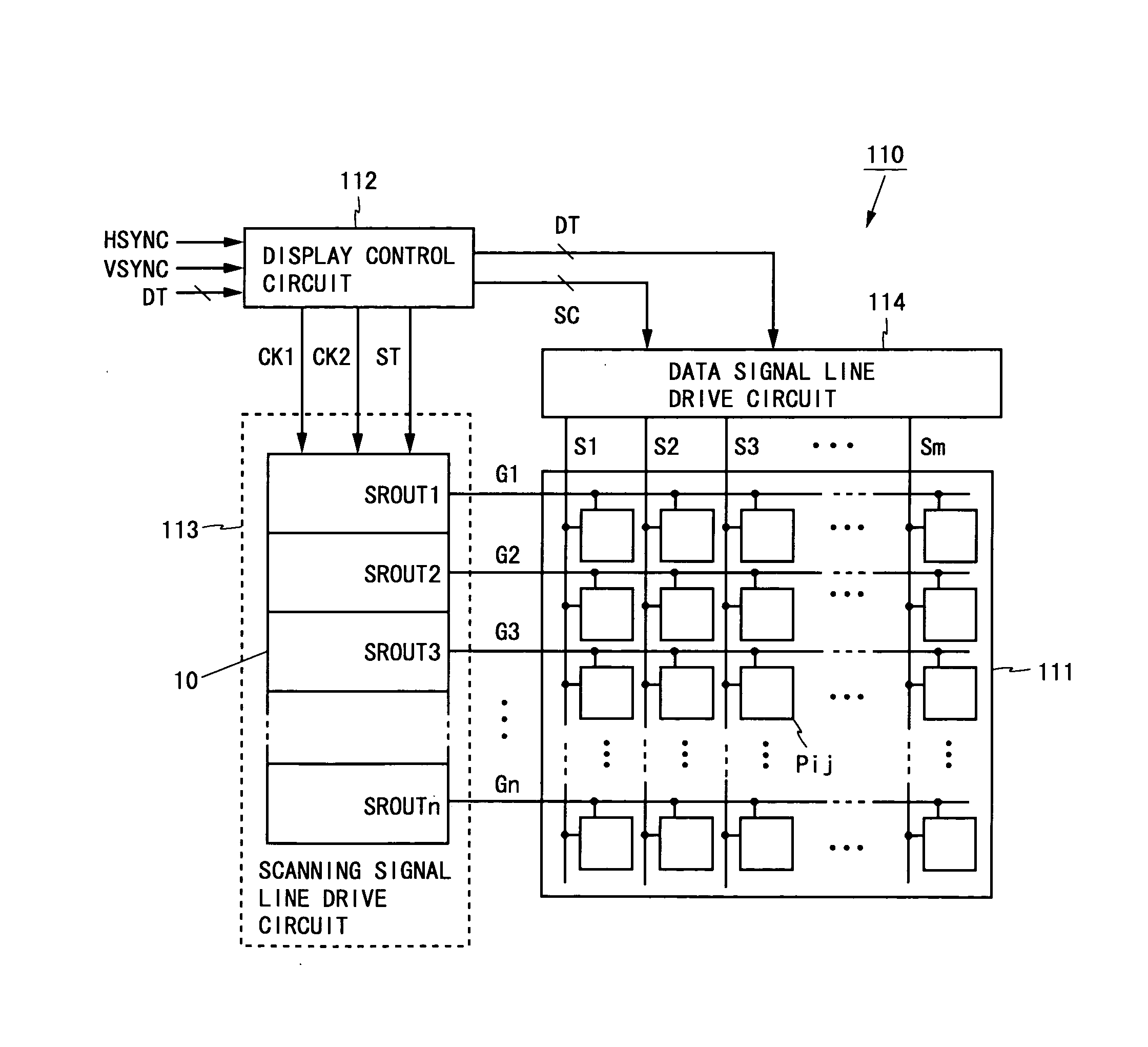
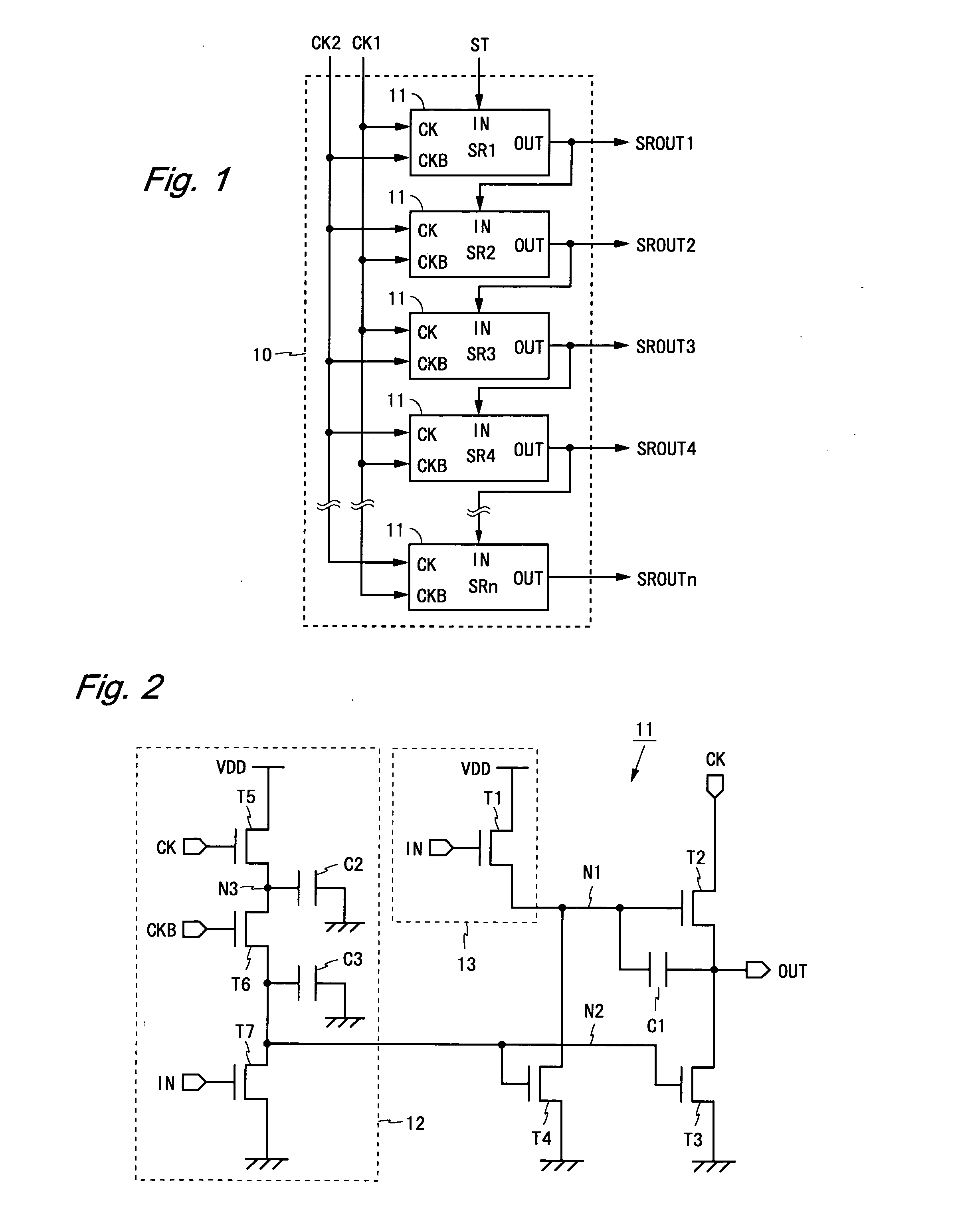
[0073]FIG. 1 is a block diagram showing a configuration of a shift register according to a first embodiment of the present invention. The shift register 10 shown in FIG. 1 has a configuration in that n (n: an integer of two or more) unit circuits 11 are cascaded. The unit circuit 11 has a clock terminal CK, a clock terminal CKB, an input terminal IN and an output terminal OUT. In the following, signals to be input / output via the respective terminals are described using designations equal to the relevant terminals. (For example, a signal to be input via the clock terminal CK is referred to as a clock signal CK.)

[0074]A start pulse ST and two-phase clock signals CK1 and CK2 are supplied externally to the shift register 10. The start pulse ST is supplied to the input terminal IN of the first unit circuit 11. The clock signal CK1 is supplied to the clock terminal CK of the odd-numbered unit circuit 11 and the clock terminal CKB of the even-numbered unit circuit 11. The clock signal CK2 ...

second embodiment

[0108]FIG. 7 is a block diagram showing a configuration of a shift register according to a second embodiment of the present invention. The shift register 20 shown in FIG. 7 includes n unit circuits 21 each having a scanning direction switch terminal UD, a scanning direction switch terminal UDB, an input terminal INu and an input terminal INd. The shift register 20 corresponds to the shift register 10 according to the first embodiment to which a function of switching a scanning direction (a direction of shift of an output signal) is added.

[0109]In the shift register 20, a direction along which a number of the unit circuit 21 becomes large (a downward direction in FIG. 7) is referred to as a forward direction, and a reverse direction thereof (an upward direction in FIG. 7) is referred to as a backward direction. The unit circuit 21 having the number which is smaller by one is referred to as a forward unit circuit, and the unit circuit 21 having the number which is larger by one is ref...

third embodiment

[0116]FIG. 9 is a block diagram showing a configuration of a shift register according to a third embodiment of the present invention. The shift register 30 shown in FIG. 9 includes n unit circuits 31 each having an initialization terminal INIT. The shift register 30 corresponds to the shift register 10 according to the first embodiment to which an initializing function is added. In the unit circuit 31, the initialization terminal INIT is supplied with an initialization signal INIT given externally.

[0117]FIG. 10 is a circuit diagram of the unit circuit 31 included in the shift register 30. The unit circuit 31 shown in FIG. 10 corresponds to the unit circuit 11 according to the first embodiment to which an initialization circuit 32 including an N-channel type transistor T13 is added. The transistor T13 has a drain terminal applied with a power supply voltage VDD, a source terminal connected to a node N2, and a gate terminal connected to the initialization terminal INIT.

[0118]When the ...


PUM


Abstract

In one embodiment of the present invention, a unit circuit of a shift register includes a bootstrap circuit configured with a transistor T1, a transistor T2 and a capacitor, a transistor T3, a transistor T4, and a reset signal generation circuit. By use of two-phase clock signals and whose high level periods do not overlap with each other, the reset signal generation circuit generates a reset signal which is at a high level in a normal state and changes to a low level when an input signal turns into the high level. During a period that the reset signal is at the high level, transistors T3 and T4 perform discharge of a node and pull-down of an output signal. Thus, it is possible to obtain a power-saving shift register that fixes an output signal at a low level in a normal state without allowing a through current to flow therein.

Description

TECHNICAL FIELD[0001]The present invention relates to a shift register, and more particularly relates to a shift register which is suitably used as a drive circuit in a display device and an imaging device, or the like.BACKGROUND ART[0002]An active matrix type display device selects pixel circuits arranged in a two dimensional manner on a row basis and writes voltages in the selected pixel circuits in accordance with display data to display an image. In order to select pixel circuits on a row basis, a shift register is used as a scanning signal line drive circuit to sequentially shift an output signal based on a clock signal. In a display device performing dot sequential driving, moreover, a data signal line drive circuit includes a shift register which is similar to that described above.[0003]In a liquid crystal display device and the like, occasionally, a drive circuit for pixel circuits is formed monolithically with the pixel circuits by a manufacturing process for forming TFTs (...

Claims


Application Information

Patent Timeline
IPC IPC(8): G09G5/00G11C19/00
CPCG09G3/3677G09G3/3688G11C19/184G09G2330/021G09G2310/0286
Inventor FURUTA, SHIGEMURAKAMI, YUHICHIROHSASAKI, YASUSHISHIMIZU, SHINSAKU
Owner SHARP KK
Why Eureka
Try Eureka