Variable power relay optical system and microscope equipped therewith

Active Publication Date: 2010-06-10
NIKON CORP
View PDF8 Cites 28 Cited by
  • Summary
  • Abstract
  • Description
  • Claims
  • Application Information

AI Technical Summary

Benefits of technology

[0014]The present invention makes it possible to provide a variable power relay optical system whose variable power lens system has

Problems solved by technology

However, in the conventional variable power relay optical system, since an exit pupil of the variable power lens system (hereinafter simply called as a “pupil of the variable power lens system”) is located inside of the var

Method used


Image

  • Variable power relay optical system and microscope equipped therewith
  • Variable power relay optical system and microscope equipped therewith
  • Variable power relay optical system and microscope equipped therewith

Examples


first embodiment

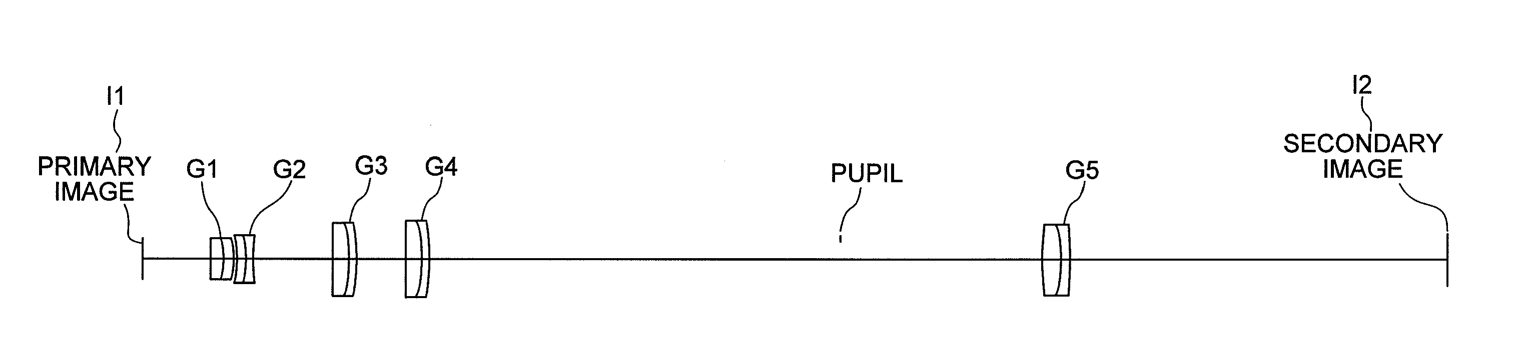
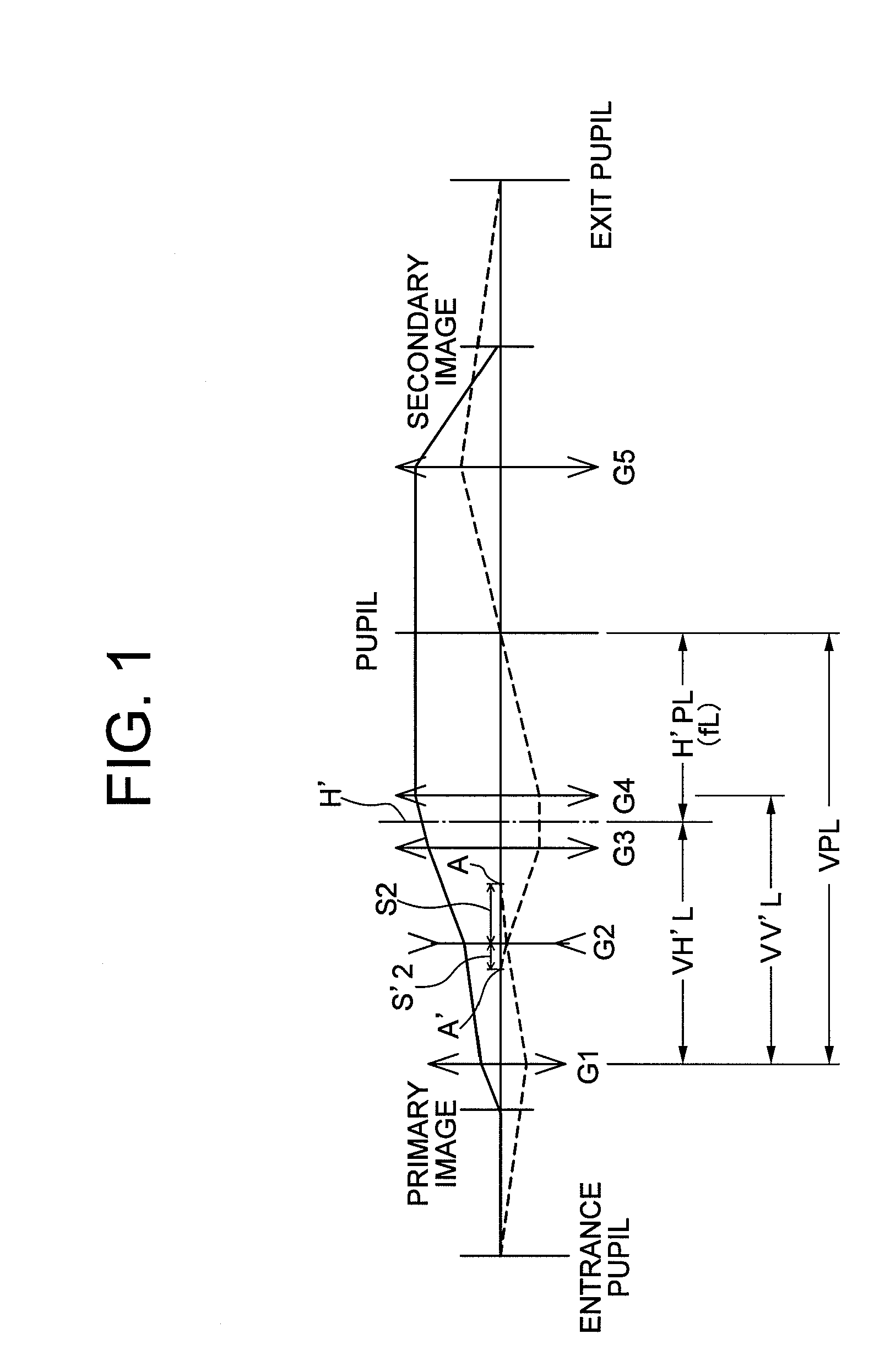
[0033]FIG. 1 is a schematic diagram explaining a basic construction of a variable power relay optical system according to a first embodiment.

[0034]The variable power relay optical system shown in FIG. 1 is, for example, an optical system for forming a secondary image on a focal plane of an eyepiece on the basis of the light from a primary image formed by an objective lens of a microscope or the like.

[0035]The variable power relay optical system is composed of, in order from the primary image side, a first lens group G1 having positive refractive power, a second lens group G2 having negative refractive power, a third lens group G3 having positive refractive power, a fourth lens group G4 having positive refractive power, and a fifth lens group G5 having positive refractive power.

[0036]Here, the first lens group G1 through the fourth lens group G4 compose a variable power lens system that receives the light from the primary image to carry out zooming the secondary image. Upon zooming f...

example 2

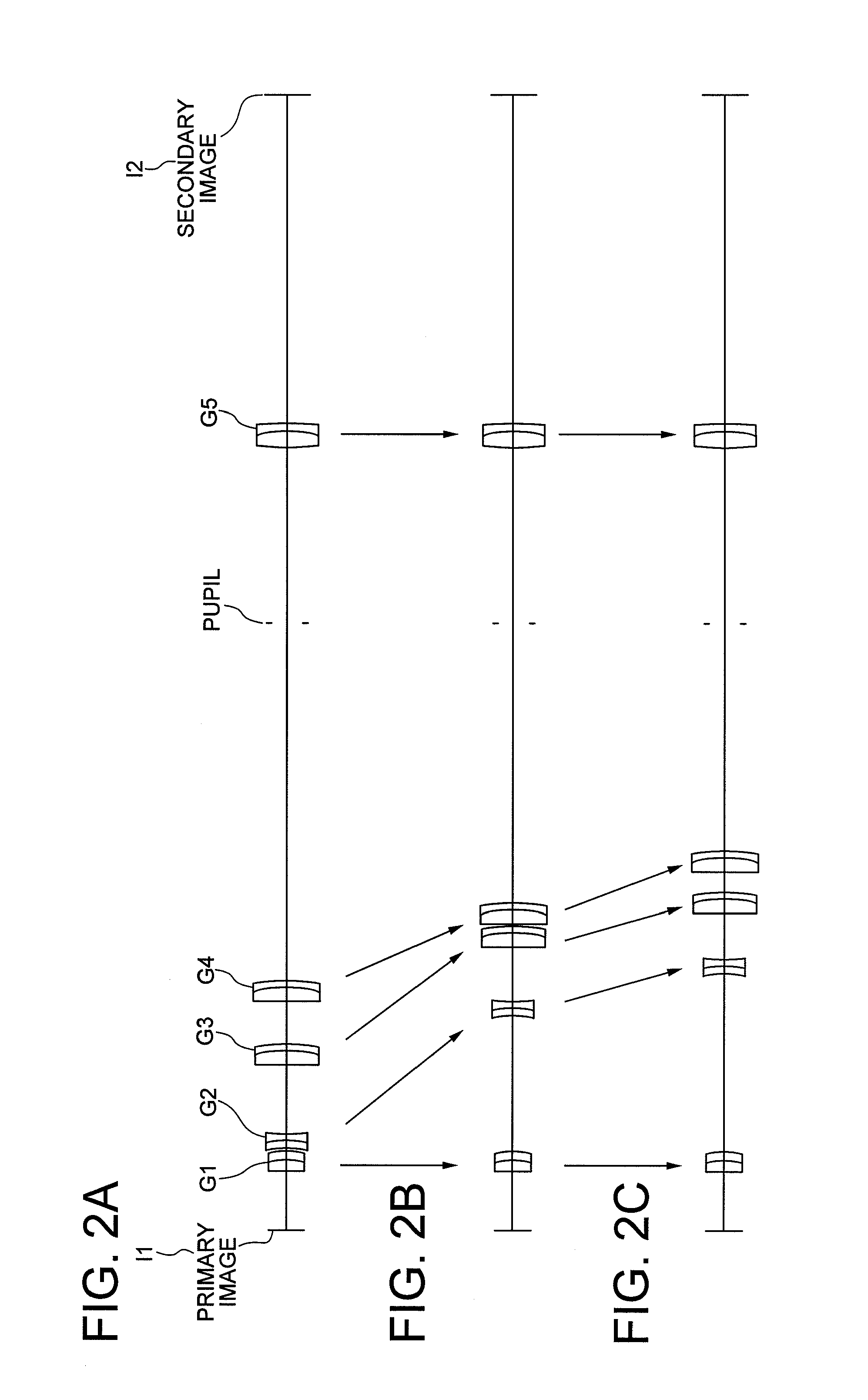
[0095]FIG. 6A is a schematic diagram showing lens configuration of a variable power relay optical system according to Example 2 in a high magnification end state. FIG. 6B is a schematic diagram showing lens configuration of a variable power relay optical system according to Example 2 in an intermediate magnification state. FIG. 6C is a schematic diagram showing lens configuration of a variable power relay optical system according to Example 2 in a low magnification end state.

[0096]The variable power relay optical system shown in FIGS. 6A through 6C is, for example, an optical system for forming a secondary image I2 on a focal plane of an eyepiece on the basis of the light from a primary image I1 formed by an objective lens of a microscope.

[0097]In FIG. 6A, the variable power relay optical system is composed of, in order from the primary image I1 side, a first lens group G1 having positive refractive power, a second lens group G2 having negative refractive power, a third lens group G...

second embodiment

[0109]FIG. 10A is a schematic diagram showing lens configuration of a microscope according to a second embodiment in a high magnification end state. FIG. 10B is a schematic diagram showing lens configuration of a microscope according to the second embodiment in a low magnification end state.

[0110]The microscope according to the second embodiment is an external phase contrast microscope 10 equipped with the variable power relay optical system according to the first embodiment. In FIGS. 10A and 10B, the solid line shown is a light ray regarding image conjugate relation between a sample S, a primary image I1 and a secondary image I2, and the dotted line is a light ray regarding pupil conjugate relation between a pupil Pob of a first objective lens Gob and a pupil P of a variable power lens system composed of a first lens group G1 through a fourth lens group G4.

[0111]In FIGS. 10A and 10B, as shown by the solid line light from the sample becomes parallel light by the first objective lens...


PUM


Abstract

A variable power relay optical system comprising: a variable power lens performing zooming a secondary image based on light from a primary image; and a rear group forming the secondary image based on the light passing through the variable power lens; the variable power lens consisting of, in order from the primary image side, a first group having positive power, a second group having negative power, a third group having positive power, and a fourth group having positive power, upon zooming from a high magnification end to a low magnification end, the fourth group being moved to the secondary image side, and a distance between the first group and the second group increasing, positions of the primary image and the secondary image, an entrance pupil of the variable power relay optical system, a pupil of the variable power lens, and an exit pupil of the variable power relay optical system being substantially kept constant, and the pupil of the variable power lens being disposed to the secondary image side of the last surface of the variable power lens.

Description

TECHNICAL FIELD[0001]The present invention relates to a variable power relay optical system having a position of an entrance pupil locating at an object side of a first surface of the lens, and extremely small variation in position of an exit pupil upon zooming in such as a zoom tube lens for a microscope, and a microscope equipped the optical system.BACKGROUND ART[0002]There has been proposed a microscope whose relay optical system is made to be a zoom lens with keeping positional relation between a primary image and a secondary image to be constant and with keeping positional relation between an entrance pupil and an exit pupil of the relay optical system to be substantially constant, for example, see Japanese Patent publication No. 3726275.[0003]However, in the conventional variable power relay optical system, since an exit pupil of the variable power lens system (hereinafter simply called as a “pupil of the variable power lens system”) is located inside of the variable power len...

Claims


Application Information

Patent Timeline
IPC IPC(8): G02B21/02G02B15/14
CPCG02B15/173G02B21/025G02B15/20G02B15/145129
Inventor NAKAYAMA, HIROAKI
Owner NIKON CORP
Why Eureka
Try Eureka