Multistage Compressor

a compressor and multi-stage technology, applied in the direction of machines/engines, liquid fuel engines, positive displacement liquid engines, etc., can solve the problems of unsatisfactory desire for compression performance and problem to be solved, and achieve the effect of improving motor efficiency, high compression performance and improving performance of multi-stage compressors

Active Publication Date: 2010-06-10
MITSUBISHI HEAVY IND LTD
View PDF2 Cites 39 Cited by
  • Summary
  • Abstract
  • Description
  • Claims
  • Application Information

AI Technical Summary

Benefits of technology

[0035]In this configuration, since the gas injection circuit is connected to and opening toward the interior of the closed housing at the position between the electric motor and the low-stage side rotary compressing mechanism, the refrigerant gas injected into the closed housing flows around the electric motor. Accordingly, the electric motor can be cooled. Consequently, the motor efficiency is improved and the performance of the multistage compressor can be improved.
[0036]According to the present invention, an excessive pressure loss is not generated during gas injection, and hence a high compression performance and a high COP (coefficient of performance) can be obtained owing to an economizer effect through gas injection. Since the pressure ratios of the low-stage side compressing mechanism and the high-stage side compressing mechanism are equivalent and the high-stage side compressing mechanism in which the

Problems solved by technology

However, those disclosed in Patent Documents 1 to 3 are intended to provide a multistage compressor for a refrigeration cycle using chlorofluorocarbon refrigerant or HFC refrigerant, and hence desired compression performance cannot be obtained necessarily even when it is applied to a supercritical refrigeration cycle (CO2 cycle) using CO2 refrigera

Method used


Image

  • Multistage Compressor
  • Multistage Compressor
  • Multistage Compressor

Examples


first embodiment

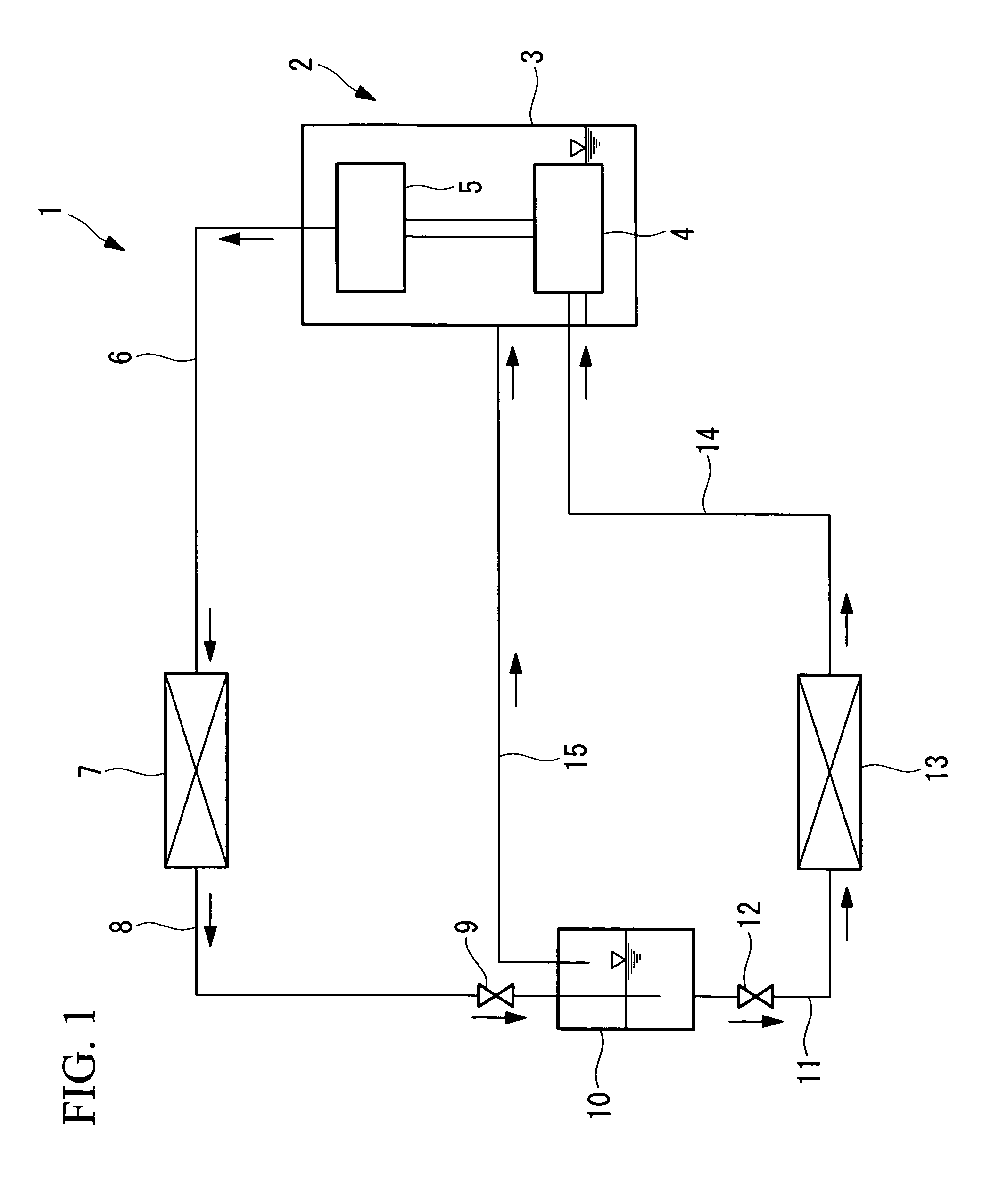
[0067]Referring to FIG. 1 to FIG. 4, a first embodiment of the present invention will be described.

[0068]FIG. 1 shows a block diagram of a CO2 cycle (a supercritical refrigeration cycle using CO2 refrigerant) 1 using a multistage compressor 2 according to the first embodiment of the present invention. The CO2 cycle 1 includes the multistage compressor 2 in which two compressing mechanisms; a low-stage side compressing mechanism 4 and a high-stage side compressing mechanism 5 are provided in one single closed housing 3. The configuration of the multistage compressor 2 will be described later in detail.

[0069]A discharge pipe 6 is connected to the high-stage side compressing mechanism 5 of the multistage compressor 2, and the other end of the discharge pipe 6 is connected to a radiator 7. High-temperature, high-pressure refrigerant gas discharged from the multistage compressor 2 is heat-exchanged with outside air sent by a radiator fan (not shown) and cooled in the radiator 7. A vapor-...

second embodiment

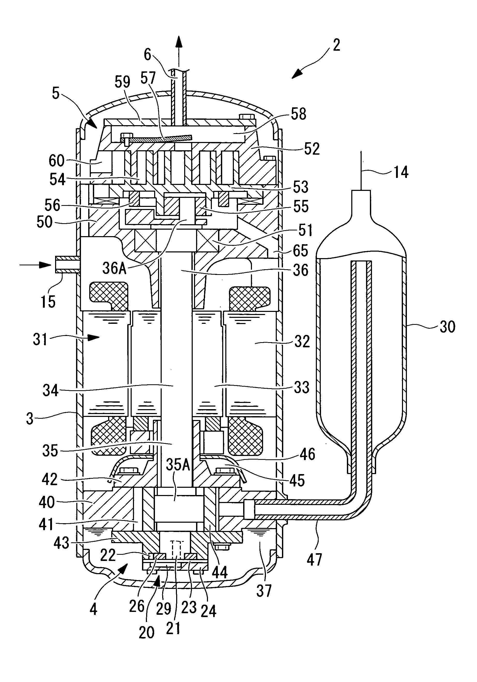
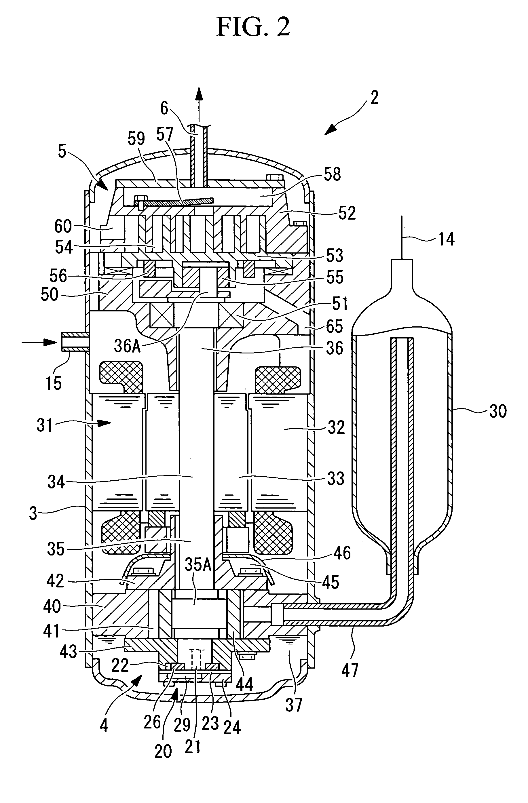
[0107]Referring now to FIG. 2 and FIG. 5, a second embodiment of the present invention will be described.

[0108]This embodiment is different from the first embodiment in that the point of connection of the gas injection circuit 15 is specified. Other points are the same as the first embodiment, and hence description thereof will be omitted.

[0109]In the high-stage side scroll compressing mechanism 5, lubricating oil which has lubricated the required points of lubrication is collected in a recess of the frame member 50, and from this recess, is dropped down to the bottom of the closed housing 3 via an oil discharge hole 65 (see FIG. 2). The gas injection circuit 15 is connected to the closed housing 3 at a position 180° opposite from the oil discharge hole 65 with respect to an axial line P of the crankshaft 34 as shown in FIG. 5.

[0110]In this manner, a sufficient distance is secured between the oil discharge hole 65 and the connecting position of the gas injection circuit 15 by connec...

third embodiment

[0113]Referring now to FIG. 6, a third embodiment of the present invention will be described.

[0114]This embodiment is different from the first embodiment in the configuration of a connecting portion of the gas injection circuit 15 connected to the closed housing 3. Other points are the same as the first embodiment, and hence description thereof will be omitted.

[0115]In this embodiment, as shown in FIG. 6, a shielding panel 66 for covering an opening of the gas injection circuit 15 at a predetermined distance is provided inside the closed housing 3 so as to oppose the point of connection of the gas injection circuit 15 to the closed housing 3.

[0116]With the provision of the shielding panel 66 as described above, refrigerant gas injected from the gas injection circuit 15 into the closed housing 3 and the lubricating oil 37 dropped down into the closed housing 3 after having lubricated the compressing mechanism 5 are separated from each other, and hence the lubricating oil 37 is preven...


PUM


Abstract

A multistage compressor employing a gas injection system for CO2 cycle that attains enhancements of compression efficiency and compression performance. The multistage compressor is multistage compressor (2) for CO2 cycle (1) adapted to carry out two-stage compression involving emitting the CO2 refrigerant gas compressed by inferior-stage side rotary compression means (4) into sealed housing (3) and having the intermediate-pressure refrigerant gas within the sealed housing (3) suctioned by superior-stage side scroll compression means (5), wherein to the sealed housing (3), there is connected gas injection circuit (15) capable of injection of intermediate-pressure CO2 refrigerant gas extracted from a refrigerant circuit into the sealed housing (3), and wherein the inferior-stage side rotary compression means (4) and the superior-stage side scroll compression means (5) are approximately identical with each other in pressure ratio and approximately equivalent with each other in displacement ratio.

Description

TECHNICAL FIELD[0001]The present invention relates to a multistage compressor suitable for applying to a supercritical refrigeration cycle (CO2 cycle) using CO2 refrigerant as an operating fluid.BACKGROUND ART[0002]In the related art, various types of multistage compressors applicable to an air conditioning apparatus are proposed. As a known example, there is a multistage compressor for two-stage compression in which a low-stage side rotary compressing mechanism is provided under an electric motor provided at a center portion in a closed housing, and compressed gas is discharged into the closed housing and intermediate pressure gas is taken into a high-stage side scroll compressing mechanism provided above the electric motor (for example, see Patent Document 1).[0003]There is also proposed in Patent Document 2 a multistage compressor for two-stage compression in which an electric motor and low-stage side and high-stage side rotary compressing mechanisms are provided in the closed ho...

Claims


Application Information

Patent Timeline
IPC IPC(8): F04B25/00
CPCF04C18/0215F04C18/0246F04C18/322F04C23/005F04C2210/261F04C29/026F04C29/028F04C29/04F04C23/008
Inventor SATO, HAJIMEKIMATA, YOSHIYUKI
Owner MITSUBISHI HEAVY IND LTD
Why Eureka
Try Eureka