Movement control method, movement manipulation apparatus, and method for manipulating movement of moving body

a technology of movement control and movement apparatus, applied in adaptive control, computer control, instruments, etc., can solve the problems of difficult to read words, difficult to perform work quickly and reliably, and pose safety problems, and achieve the effect of reducing cost, ensuring safety and ensuring accuracy

Inactive Publication Date: 2010-06-10
GOGOU CO LTD
View PDF12 Cites 36 Cited by
  • Summary
  • Abstract
  • Description
  • Claims
  • Application Information

AI Technical Summary

Benefits of technology

[0164]As a result, the moving body is monitored while the manipulation switch for the direction in which the moving body is to be moved is pressed from among the four manipulation switches provided to the side faces of the remote casing, and when the direction in which the moving body is to be moved is oblique with respect to the cuboid remote casing, the moving body is moved in a zigzag pattern within the horizontal plane by alternately pressing two manipulation switches, allowing the operator to move the moving body to the desired location without taking his eye off the moving body. The moving body can be lowered to the desired location by operating the up and down switch on the remote casing and lowering

Problems solved by technology

Such overhead cranes are conventionally manipulated by successively pressing the six buttons (east, west, north, south, up, and down) on a wired remote apparatus hanging down from the winder, but when the load is large, there is the possibility that the load hanging from the winder will come into contact with the person manipulating the wired remote apparatus hanging down form the winder, which poses safety problems.
However, with a wired type of remote apparatus, putting aside wireless types for the moment, when used for an overhead crane or the like that is used in a painting plant or the like, the push buttons on the remote apparatus can become soiled by paint and so forth, making it difficult to read the words (east, west, north, south, up, and down) written on the buttons, and since the operator is typically looking at the remote apparatus while pressing the buttons and manipulating the apparatus, he cannot watch the movement of the load being conveyed by the overhead crane, which not only makes it difficult to perform the work quickly and reliably, but also poses the risk that the operator of the remote apparatus may not notice if the load gets too close.
Furthermore, if the operator is a novice, he will not instantly be able to tell which way is east, west, north, or south, so a problem is that the work cannot be performed quickly and reliably.
Also, These problems are not unique to three-dimensional movement apparatus, and also occur with other types of movement apparat

Method used


Image

  • Movement control method, movement manipulation apparatus, and method for manipulating movement of moving body
  • Movement control method, movement manipulation apparatus, and method for manipulating movement of moving body
  • Movement control method, movement manipulation apparatus, and method for manipulating movement of moving body

Examples


embodiment 1

[0177]First, the three-dimensional movement apparatus pertaining to Embodiment 1 of the presently disclosed subject matter will be described through reference to FIGS. 1 to 4.

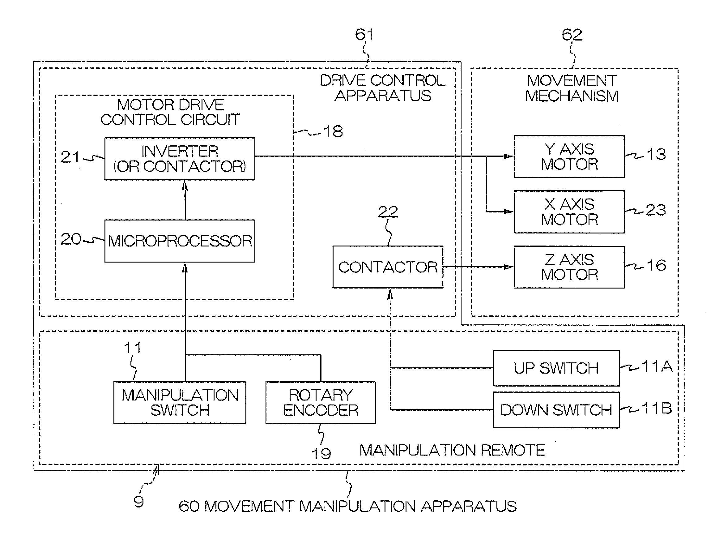
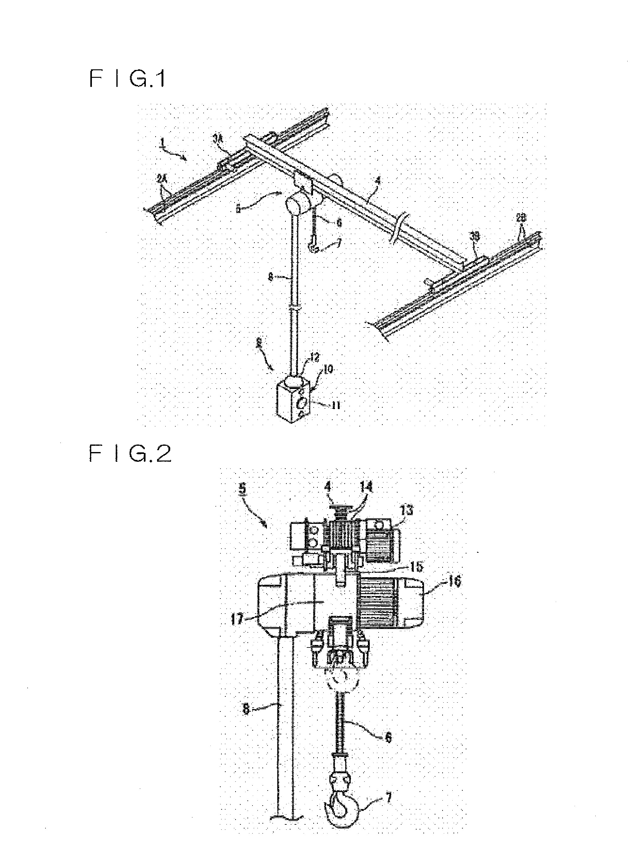
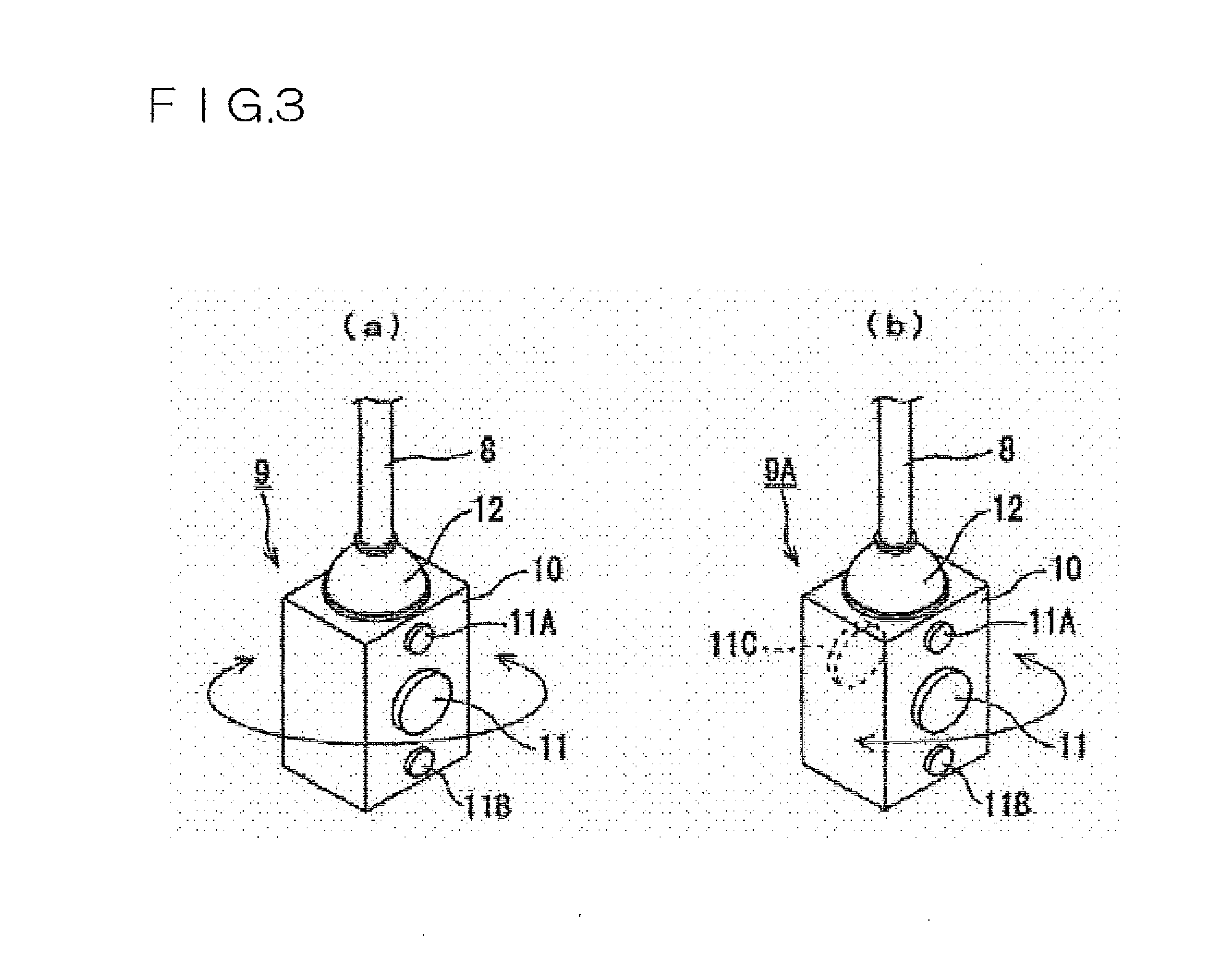
[0178]FIG. 1 is an oblique view of the overall configuration of an overhead crane, which is an example of the three-dimensional movement apparatus pertaining to Embodiment 1 of the presently disclosed subject matter. FIG. 2 is a diagram of the structure of a lifting device of an overhead crane, which is an example of the three-dimensional movement apparatus pertaining to Embodiment 1 of the presently disclosed subject matter. FIG. 3(a) is an oblique view of the remote casing portion of a manipulation remote in a three-dimensional movement apparatus pertaining to Embodiment 1 of the presently disclosed subject matter, and FIG. 3(b) is an oblique view of the remote casing portion of a manipulation remote in a three-dimensional movement apparatus pertaining to a modification of Embodiment 1 of the presently disclo...

embodiment 2

[0210]Next, an overhead crane will be described through reference to FIGS. 5 and 6, as an example of a three-dimensional movement apparatus pertaining to Embodiment 2 of the presently disclosed subject matter.

[0211]FIG. 5 is an oblique view of the overall configuration of an overhead crane, which is an example of the three-dimensional movement apparatus pertaining to Embodiment 2 of the presently disclosed subject matter.

[0212]FIG. 6 is an oblique view of the manipulation remote in the three-dimensional movement apparatus pertaining to Embodiment 2 of the presently disclosed subject matter.

[0213]The overhead crane 1A pertaining to Embodiment 2 of the presently disclosed subject matter has the same external appearance as the overhead crane 1 in Embodiment 1 shown in FIG. 1, except for the portion of a manipulation remote 35, so portions that are the same are numbered the same as in FIG. 1 and will not be described in detail again. The constitution of the motor drive control circuit i...

embodiment 3

[0224]An overhead crane will now be described through reference to FIGS. 7 to 9, as an example of the three-dimensional movement apparatus pertaining to Embodiment 3 of the presently disclosed subject matter.

[0225]FIG. 7 is an oblique view of the overall configuration of an overhead crane, which is an example of the three-dimensional movement apparatus pertaining to Embodiment 3 of the presently disclosed subject matter. FIG. 8 is an oblique view of the manipulation remote in the three-dimensional movement apparatus pertaining to Embodiment 3 of the presently disclosed subject matter. FIG. 9 is an oblique view of the manipulation remote in a modification of the three-dimensional movement apparatus pertaining to Embodiment 3 of the presently disclosed subject matter.

[0226]The overhead crane 1B pertaining to Embodiment 3 of the presently disclosed subject matter has the same external appearance as the overhead crane 1 in Embodiment 1 shown in FIG. 1 except for a manipulation remote 40...


PUM


Abstract

In a movement control apparatus manipulation can be carried out while watching the movement of the moving body, without needing to watch one's hands, so even a novice operator can perform the manipulation easily, safely, reliably, and quickly. The apparatus can include a signal transmission cable, a casing of a manipulation remote controller disposed at one end of the cable, a rotary encoder that produces a signal corresponding to the direction of the casing, and a motor drive control circuit that is disposed on the other side of the cable and controls the movement of a moving body on the basis of a signal corresponding to the direction of the casing. The signal corresponding to the direction of the casing can be supplied from the rotary encoder, through the cable, to the motor drive control circuit. Therefore, the operator can hold down a manipulation switch without looking at his hands and thereby adjust the direction of the casing of the manipulation remote controller while looking at the movement direction of a load.

Description

TECHNICAL FIELD[0001]The presently disclosed subject matter relates to a technique for manipulating the movement of a moving body, and more particularly relates to a movement control method, movement manipulation apparatus, movement manipulation method, and so forth, with which the movement of a moving body can be manipulated easily, safely, reliably, and quickly, even by a novice operator.[0002]Definitions and interpretations of the terms used in the presently disclosed subject matter are listed below.[0003](1) “Remote” is an abbreviation for a remote controller in the sense of an apparatus for remote manipulating, remote controlling, or other such manipulations, or an abbreviation for a remote control in the sense of an apparatus for remote manipulate, remote controlling, or other such manipulations. A difference in signal transmission method (wireless versed wired) does not affect the definition or interpretation of “remote” unless otherwise specified.[0004](2) Unless otherwise s...

Claims


Application Information

Patent Timeline
IPC IPC(8): G05D3/00
CPCB66C13/44B66C13/40G05B15/02G05D3/10
Inventor YAMAGUCHI, FUJIOKIOGAWA, KOUJI
Owner GOGOU CO LTD
Why Eureka
Try Eureka