
Inertia estimating controller and control system

a controller and inertia technology, applied in adaptive control, program control, instruments, etc., can solve the problems of difficult to determine the inerti difficult to calculate the inertia of the article to be driven, and difficult to determine the inertia in a short period of tim

Active Publication Date: 2010-06-17
FANUC LTD
View PDF7 Cites 31 Cited by
  • Summary
  • Abstract
  • Description
  • Claims
  • Application Information

AI Technical Summary

Benefits of technology

[0014]The object of the present invention is to provide a controller and a control system for estimating the inertia, capable of improving at least one of the above four points.

Problems solved by technology

However, it is not easy to determine the inertia of the article to be driven.
For example, it is difficult to calculate the inertia of an article to be driven if the article has a complicated structure.
However, it is not easy to determine the inertia in a short period of time.
Therefore, it is necessary to operate the electric motor for a relatively long period of time.
In particular, in a machine tool, the operation range of a drive axis may be limited, whereby it may be difficult to obtain the operation range sufficient to estimate the inertia.
In addition, when a workpiece is frequently replaced with another, it may be difficult to obtain sufficient time for carrying out the particular operation required to estimate the inertia.
In the inertia is measured after the inertia is changed by attaching a workpiece, it maybe difficult to stably control the motor by a control gain before the inertia is changed.
Therefore, such noise may deteriorate the accuracy of the inertia.

Method used


Image

  • Inertia estimating controller and control system
  • Inertia estimating controller and control system
  • Inertia estimating controller and control system

Examples


Embodiment Construction

[0028]Hereinafter, each embodiment of the present invention will be explained with reference to the drawings.

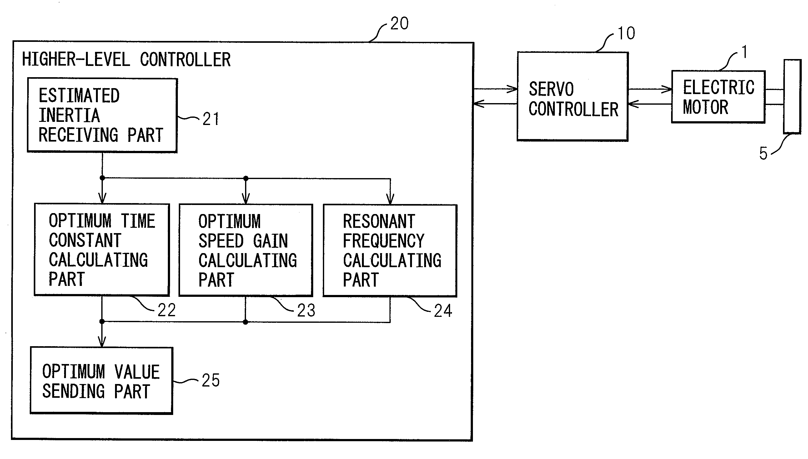
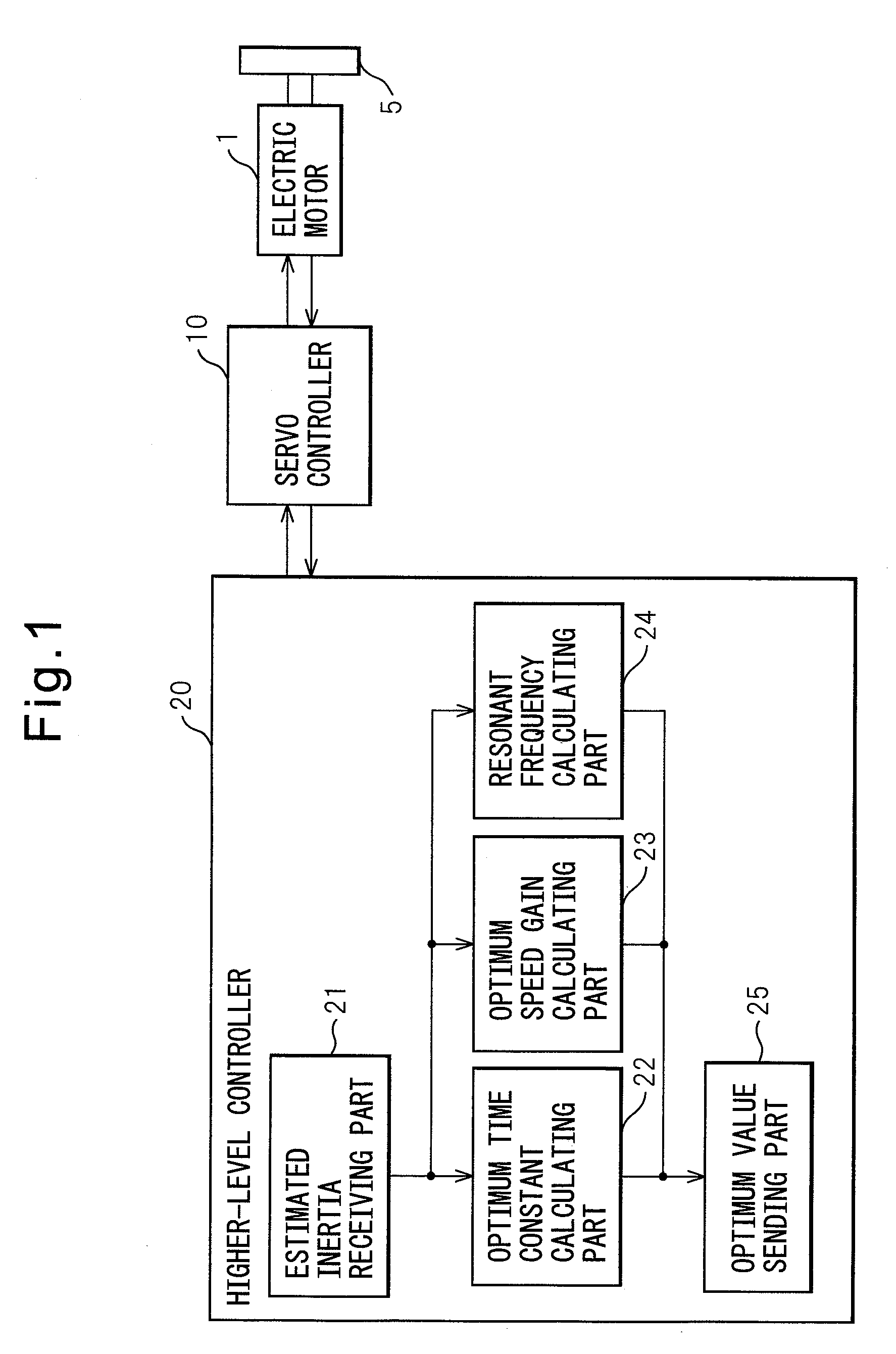
[0029]FIG. 1 is a block diagram of a control system according to an embodiment of the invention. As shown, an article to be controlled in this embodiment is an electric motor 5 which drives an article 5. Electric motor 1 may be used to, for example, change the position and / or the orientation of a table which holds a workpiece in a machine tool, or rotate a robot arm. Article 5 to be driven by electric motor 1 may include the table, the robot arm or the workpiece attached thereto. Further, article 5 may include a movable part of electric motor 1.

[0030]The position, a speed and a torque of electric motor 1 are controlled by a servo controller 10. To servo controller 10, a higher-level controller 20 or an external device, such as a CNC controller which outputs commands of the position, the speed and the torque of electric motor 1 depending on a working process, is connected. To ...


PUM


Abstract

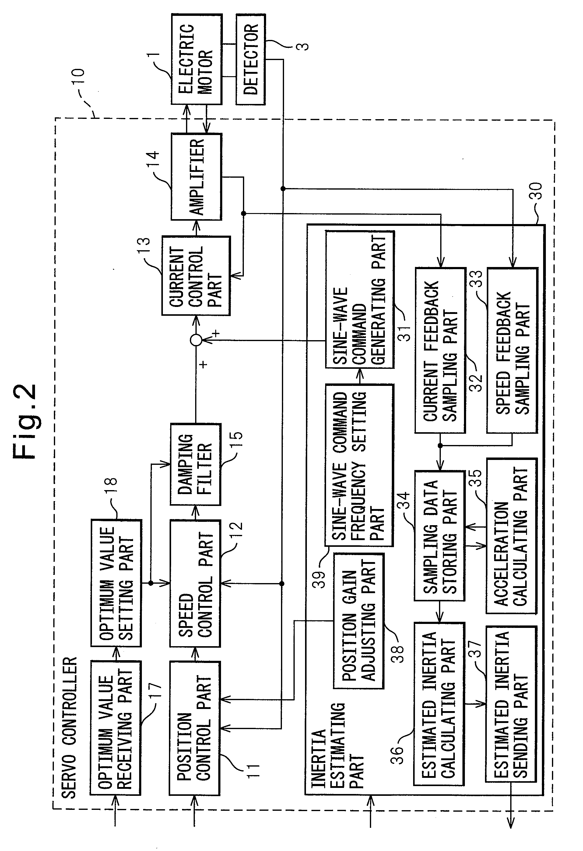
A controller and a control system capable of estimating inertia of an article to be driven in a short period of time, with a small operation range of an electric motor. The controller for the motor has an inertia estimating part which includes a sine-wave command generating part which adds a sine-wave command to a torque command for the motor; a current feedback sampling part which obtains a current value of the motor; a speed feedback sampling part which obtains a speed feedback of the motor; an acceleration calculating part which calculates an acceleration value based on the speed feedback; and an estimated inertia calculating part which estimates the inertia of the article, based on a representative current value, a representative acceleration value and a torque constant of the motor, which are calculated from current and acceleration values in a plurality of cycles of the sine-wave command and stored in a sampling data storing part.

Description

RELATED APPLICATIONS[0001]The present application claims priority from Japanese Patent Application No. 2008-320088, filed on Dec. 16, 2008, the entire content of which is fully incorporated herein by reference.BACKGROUND OF THE INVENTION[0002]1. Field of the Invention[0003]The present invention relates to a controller and a control system for an electric motor, which drives a mechanical element of an industrial machine, such as a machine tool, and in particular, relates to a controller and a control system, which estimates the inertia of an article to be driven by the electric motor.[0004]2. Description of the Related Art[0005]In a machine tool or the like, it is important to know the inertia of an abject to be driven by an electric motor for determining a process condition or the like, and for controlling the motor with high accuracy. For example, when a time constant of an acceleration / deceleration command as the process condition is to be determined, it is advantageous to correct...

Claims


Application Information

Patent Timeline
IPC IPC(8): G05B13/02H02P29/00
CPCG05B19/404G05B2219/37621G05B2219/37388
Inventor OKITA, TADASHITOYOZAWA, YUKIOSONODA, NAOTO
Owner FANUC LTD
Learn More