Improved signal processing for optical computing system

a technology of optical computing and signal processing, applied in the direction of optical radiation measurement, instruments, spectrometry/spectrophotometry/monochromators, etc., can solve the problem of unacceptably inaccurate estimation, inability to accurately measure the data relating to one of these factors, and difficulty in conversion of light intensity measurement to information

Active Publication Date: 2010-06-17
HALLIBURTON ENERGY SERVICES INC
View PDF3 Cites 70 Cited by
  • Summary
  • Abstract
  • Description
  • Claims
  • Application Information

AI Technical Summary

Benefits of technology

[0026]In view of the recognized features encountered in the prior art and addressed by the present subject matter, a method of high-speed processing and monitoring of a plurality of sample portions of products has been developed. In accordance with an exemplary configuration a plurality of portions of pharmaceutical product may be moved past an inspection point where at least one portion of the pharmaceutical product is illuminated with a spectral-specific light though an optic window. The window may be configured to focus the spectral-specific light onto a portion at the inspection point. Reflected light carrying information about the portion through at least one multivariate optical element falling on a first detector produces a first signal. A portion of the spectral-specific light is deflected toward a second detector, and at least one selected property of the portion is determined at high speed based upon the detector outputs as the portion moves past the inspection point. The disclosed method also includes measuring and recording the temperature of the system to enable compensation or correction of the detector outputs based on the system temperature.
[0027]The product portions may correspond to pharmaceutical tablets, trays or other containers of powders, o

Problems solved by technology

In general, measurement of light intensity may be difficult to convert to information due to contained interfering data.
It is often impossible to adequately measure the data relating to one of these factors since the contributions from other factors may be unknown.
Depending on the circumstances, however, the estimate may be unacceptably inaccurate since factors other than ethylene may affect the intensity of the wavelength bands.
Unfortunately, however, charge couple devices and their required operational inst

Method used


Image

  • Improved signal processing for optical computing system
  • Improved signal processing for optical computing system

Examples


Embodiment Construction

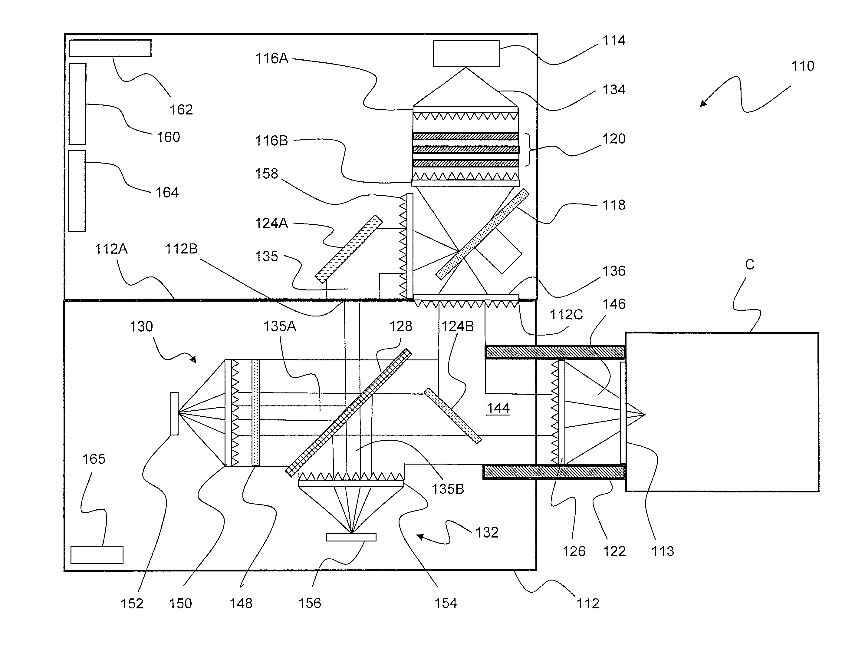
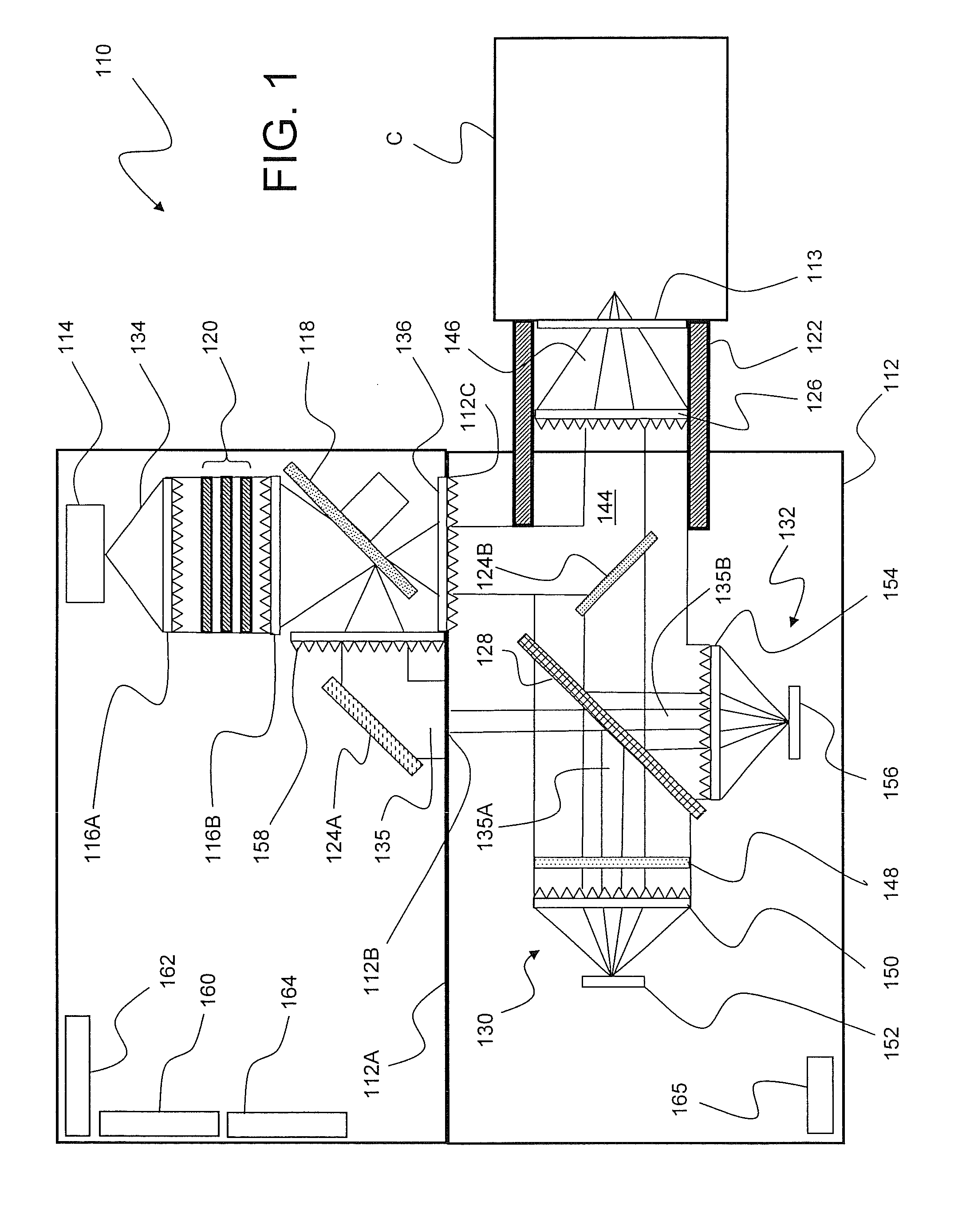
[0032]As discussed in the Summary of the Invention section, the present subject matter is particularly concerned with an improved methodology for high-speed processing and monitoring of a plurality of sample product portions.

[0033]Selected combinations of aspects of the disclosed technology correspond to a plurality of different embodiments of the present invention. It should be noted that each of the exemplary embodiments presented and discussed herein should not insinuate limitations of the present subject matter. Features or steps illustrated or described as part of one embodiment may be used in combination with aspects of another embodiment to yield yet further embodiments. Additionally, certain features may be interchanged with similar devices or features not expressly mentioned which perform the same or similar function.

[0034]As used herein, the term “light” is broadly used to mean any form of radiation or radiative energy including, but not limited to, visible light or light ...


PUM


Abstract

The present subject matter relates to methods of high-speed analysis of product samples during production of the product. Light is directed to a portion of a product under analysis and reflected from or transmitted through the product toward optical detectors. Signals from the optical detectors are compared to determine characteristics of the product under analysis. Temperature within the monitoring system may be monitored in order to provide compensation for the signals produced by the optical detectors. The products under analysis may be stationary, moved by an inspection point by conveyor or other means, or may be contained within a container, the container including a window portion through which the product illuminating light may pass.

Description

[0001]This application claims priority under 35 USC 119(e) of Provisional Patent Application Ser. No. 60 / 856,192 filed Nov. 2, 2006, entitled “IMPROVED SIGNAL PROCESSING FOR OPTICAL COMPUTING SYSTEM,” which is hereby incorporated by reference in its entirety.FIELD OF THE INVENTION[0002]The present subject matter relates to system design, fabrication and operation of multivariate optical elements. More particularly, the present subject matter relates to methodologies of using multivariate optical computing systems to illuminate a sample such that information about the sample can be analyzed from reflected or transmitted light in real time or near real time.BACKGROUND OF THE INVENTION[0003]Light conveys information through data. When light interacts with matter, for example, it carries away information about the physical and chemical properties of the matter. A property of the light, for example, its intensity, may be measured and interpreted to provide information about the matter wi...

Claims


Application Information

Patent Timeline
IPC IPC(8): G01N21/55G01N21/59
CPCG01J3/02G01J3/021G01J3/0229G01J3/0232G01J3/0235G01N2201/1293G01J3/0286G01J3/08G01J3/28G01J3/42G01J2003/1213G01J3/0243
Inventor MYRICK, MICHAEL L.FREESE, ROBERT P.SOLTMANN, WILLIAMPERKINS, DAVID L.
Owner HALLIBURTON ENERGY SERVICES INC
Why Eureka
Try Eureka