Calibration method, communication system, frequency control method, and communication device

a communication system and frequency control technology, applied in the field of calibration methods, can solve the problems of difficult to easily obtain the phase difference just from the distance, various reflections, and the inability to perform a highly accurate transmission beamforming, etc., to achieve the effect of simplifying wireless communication devices and simple digital processing

Inactive Publication Date: 2010-06-17
MITSUBISHI ELECTRIC CORP
View PDF8 Cites 231 Cited by
  • Summary
  • Abstract
  • Description
  • Claims
  • Application Information

AI Technical Summary

Benefits of technology

[0028]With the invention, on performing a self-calibration in which calibration is performed without communicating with another device, the calibration can be ...

Problems solved by technology

Consequently, how to perform a highly accurate transmission beamforming is an important issue in the future.
However, in real life, even if reciprocity is satisfied in actual channels from an antenna end of the transmitter to an antenna end of the receiver, due to the characteristics difference between analog devices in the transmitter and receiver circuits, complete reciprocity is not established in a channel measured in a digital domain (hereinafter, referred to as a measurement channel).
However, when the surrounding propagation environment of a wir...

Method used


Image

  • Calibration method, communication system, frequency control method, and communication device
  • Calibration method, communication system, frequency control method, and communication device
  • Calibration method, communication system, frequency control method, and communication device

Examples


eighth a embodiment

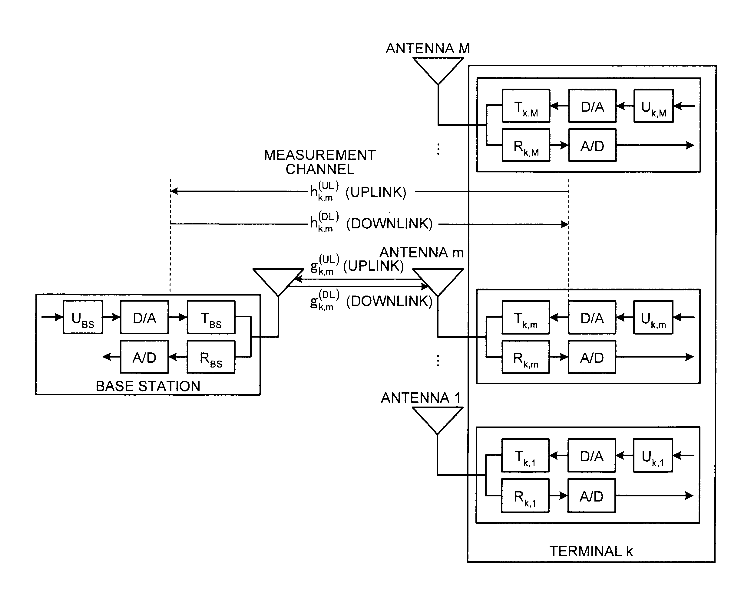
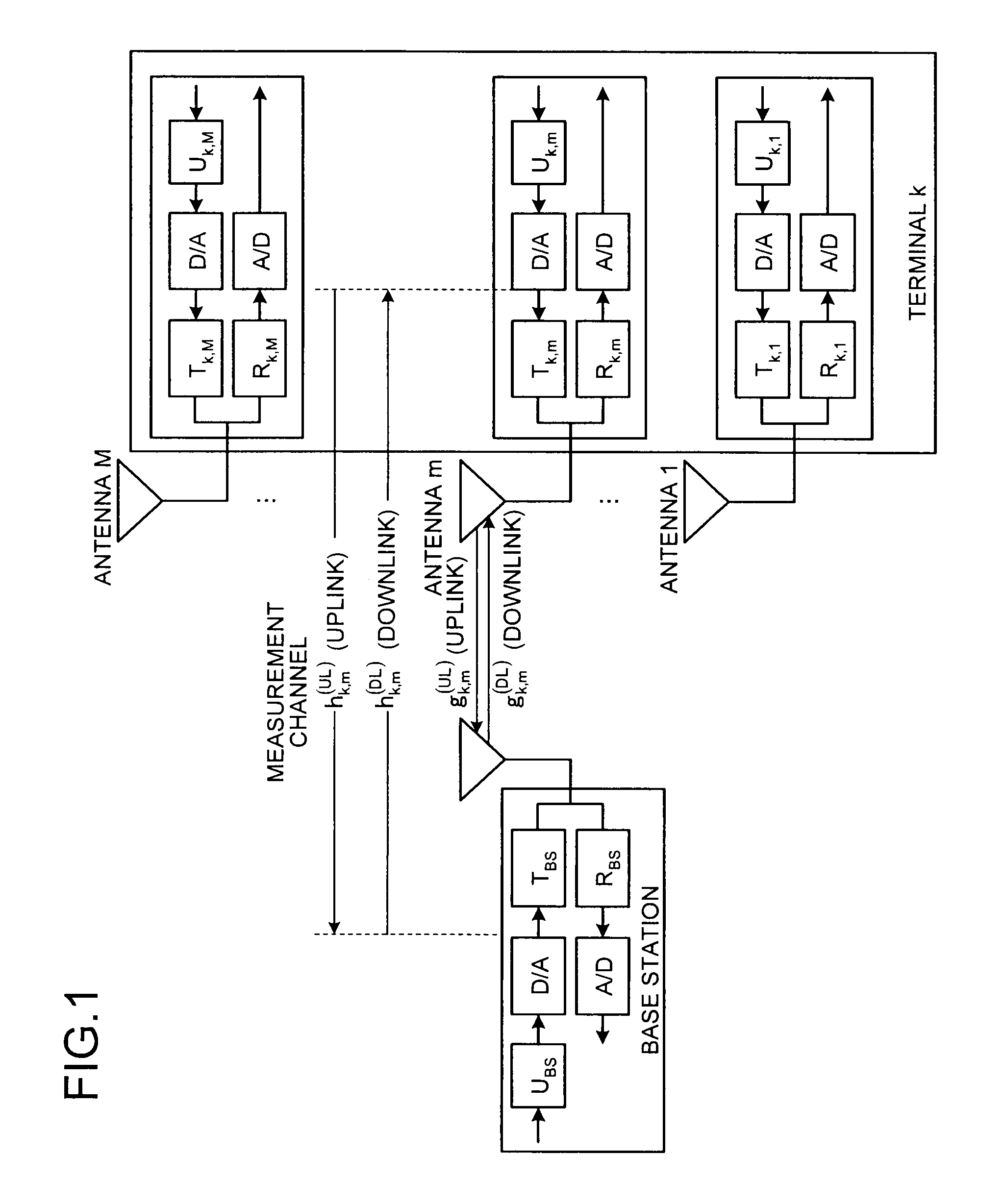
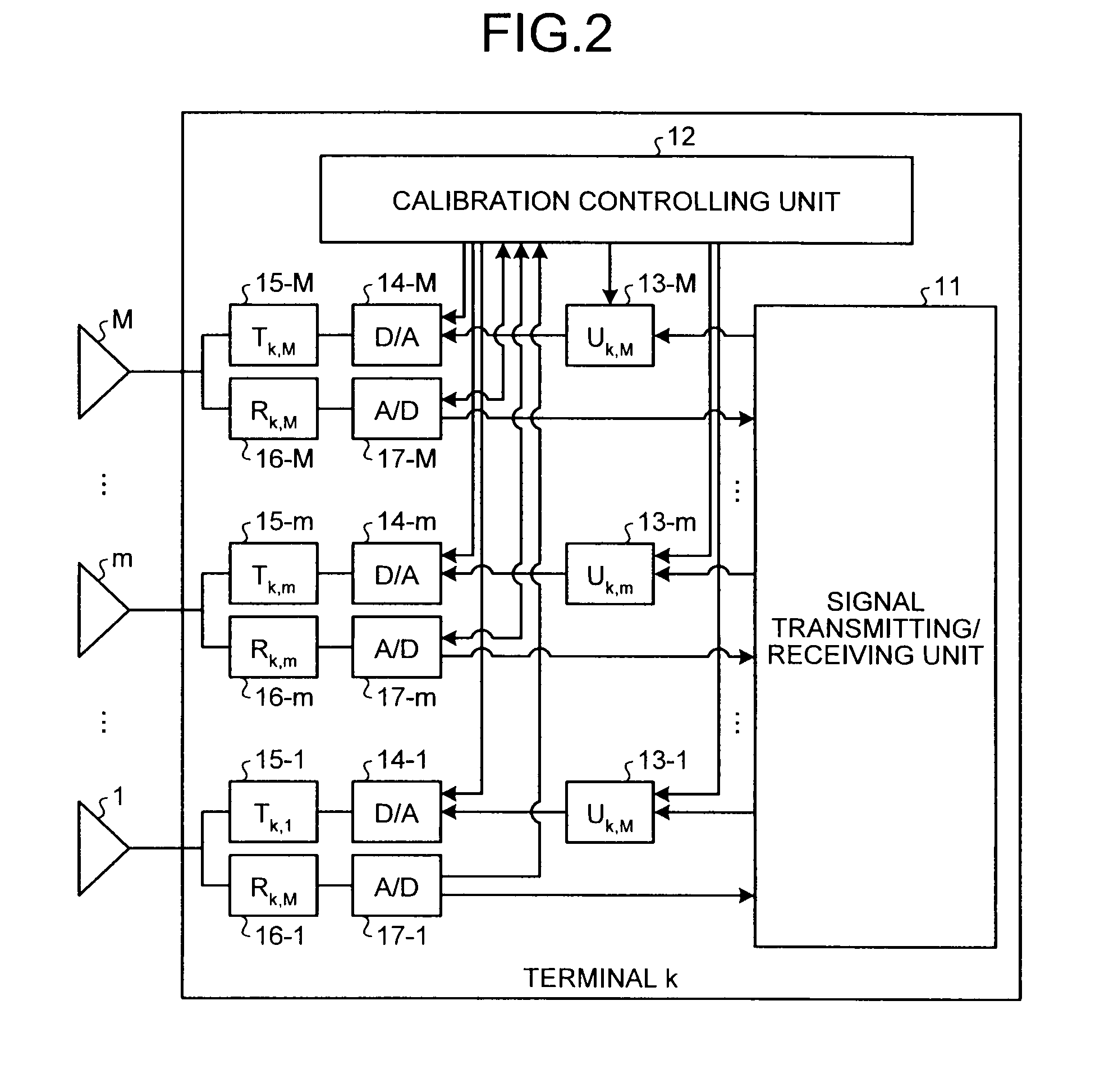
[0257]An eighth A embodiment will now be described. In the present embodiment, a transmission method of a pilot signal different from the transmission method of the pilot signal according to the seventh embodiment will be described. The structures of the terminal k and the base station according to the present embodiment are the same as those in the fourth embodiment.

[0258]In the uplink and downlink pilot transmissions according to the fourth to the sixth embodiments, the channel in the same pathway is required to have a small variation. If the carrier frequencies of the base station and the terminal can be regarded as the same, channels in the different pathways may be measured in the different environments. An environment where the carrier frequencies of the base station and the terminal are the same is achieved, by using a highly accurate frequency oscillator such as a rubidium oscillator, or by performing an ultra accurate carrier frequency control, which will be described in th...

eighth b embodiment

[0271]An eighth B embodiment will now be described. In the present embodiment, a transmission method of a pilot signal different from the transmission method of the pilot signal according to the eighth A embodiment will be described. The structures of the terminal k and the base station according to the present embodiment are the same as those in the fourth embodiment.

[0272]Unlike the eighth A embodiment, if a channel is measured at different times, while the carrier frequencies between the base station and the terminal are different, the phase rotation corresponding to the carrier frequency offset is added to the channel measurement. As a result, the channel measurement and the correction value uk,m calculated based on the channel measurement include different phase offsets, corresponding to the time. Accordingly, if the channel is measured at different times for each antenna, the relative phase relationship between the antennas is not corrected appropriately.

[0273]To prevent such ...

eighth c embodiment

[0276]An eighth C embodiment will now be described. In the present embodiment, a transmission method of a pilot signal different from the transmission methods of a pilot signal according to the eighth A and the eighth B embodiments will be described. The structures of the terminal k and the base station according to the present embodiment are the same as those in the fourth embodiment.

[0277]As described in the eighth B embodiment, if the channels are measured at different times, while the carrier frequencies between the base station and the terminal are different, the phase rotation corresponding to the carrier frequency offset is added to the channel measurement. As a result, if the channel corresponding to the different antenna is measured at different times, the correction values uk,m include different phase offsets based on the channel measurement time, and the relative phase relationship between the antennas is not appropriately corrected. However, as explained in the eighth B ...


PUM


Abstract

A calibration method according to the present invention includes a step of first channel estimating for transmitting a pilot signal from a first antenna and receiving the pilot signal at a second antenna different from the first antenna to calculate a first channel estimation value; a step of second channel estimating for transmitting a plot signal from the second antenna and receiving the pilot signal at the first antenna to calculate a second channel estimation value; and a step of correction coefficient calculating for calculating, by using the first and second channel estimation values, a correction coefficient.

Description

TECHNICAL FIELD[0001]The present invention relates to a digital processing for smoothly transmitting and receiving signals in wireless communications.BACKGROUND ART[0002]Demands for high-speed wireless communications are increasing, and transmission technologies for high-speed wireless communications are in need. Accordingly, in these days, a technology in which transmitters and receivers that can perform high-speed signal transmission by using a plurality of antennas has been widely studied. In future mobile communications, an environment where a base station performs simultaneous spatial multiplexing on a plurality of terminals by using a transmission beam may become available. Reduction in transmission power required for communications at a terminal can be achieved by performing appropriate transmission beamforming. Consequently, how to perform a highly accurate transmission beamforming is an important issue in the future.[0003]The same frequency is alternately used in the uplink...

Claims


Application Information

Patent Timeline
IPC IPC(8): H04J1/16H04J3/00H04W72/00H04J99/00
CPCH04L25/0224H04L27/2647H04B17/12H04W52/325H04W52/241
Inventor HARA, YOSHITAKATAIRA, AKINORITAJIMA, KENICHIKIHIRA, KAZUNARITAKANO, MICHIAKIISHIOKA, KAZUAKINOUDA, YASUNORI
Owner MITSUBISHI ELECTRIC CORP
Why Eureka
Try Eureka