Subcritical reactivity measurement method

a nuclear reactor and multiplication factor technology, applied in the field of subcritical reactivity measurement method, can solve the problems of general insensitivity to accurately detect low-level neutron flux emitted in the source range, no direct method for measuring when, and subject to much uncertainty

a nuclear reactor and multiplication factor technology, applied in the field of subcritical reactivity measurement method, can solve the problems of general insensitivity to accurately detect low-level neutron flux emitted in the source range, no direct method for measuring when, and subject to much uncertainty

US20100150295A1Active Publication Date: 2010-06-17WESTINGHOUSE ELECTRIC CORP

Image

  • Subcritical reactivity measurement method
  • Subcritical reactivity measurement method
  • Subcritical reactivity measurement method

Examples


Embodiment Construction

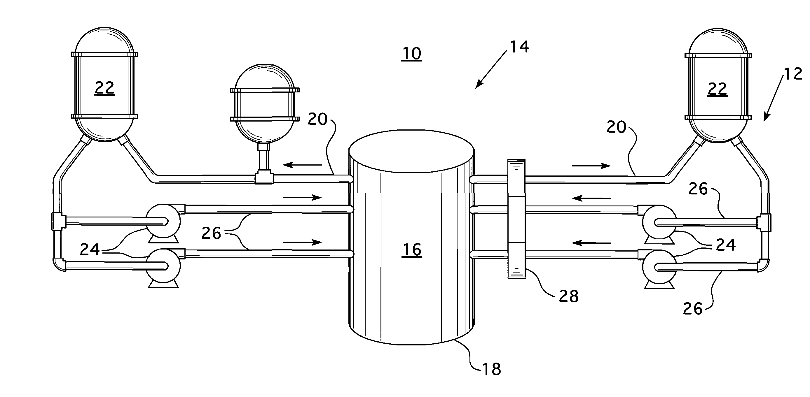
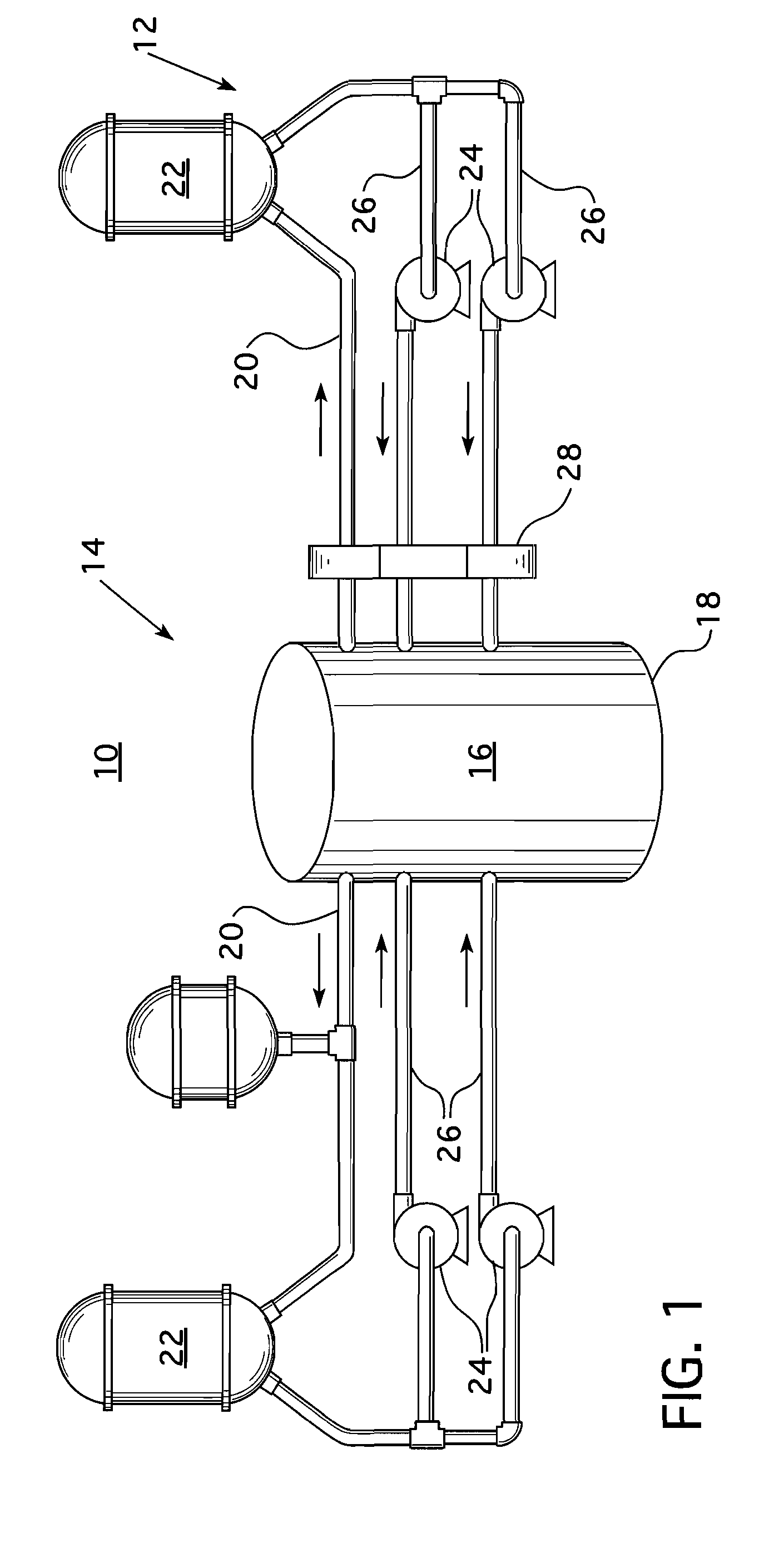
[0016]FIG. 1 illustrates the primary side of a nuclear electric power generating plant 10 in which a nuclear steam supply system 12 supplies steam for driving a turbine generator (not shown) to produce electric power. The nuclear steam supply system 12 has a pressurized water reactor 14 which includes a reactor core 16 housed within a pressure vessel 18. Fission reactions within the reactor core 16 generate heat, which is absorbed by a reactor coolant, like water, which is passed through the core. The heated coolant is circulated through hot leg piping 20 to a steam generator 22. Reactor coolant is returned to the reactor 14 from the steam generator 22 by a reactor coolant pump 24 from the cold leg piping 26. Typically, a pressurized water reactor has at least two and often three or four steam generators 22 each supplied with heated coolant through a hot leg 20, forming with the cold leg 26 and the reactor coolant pump24, a primary loop. Each primary loop supplies steam to the turbi...


PUM


Abstract

A method of determining the spatially corrected inverse count ratio (SCICR) used to determine reactor criticality, which subtracts a background noise signal from the source range detector output. The method monitors the source range detector signal at two different core temperature levels during a transient portion of the detector output as the power output of the reactor is increased in the source range. This information is employed to analytically determine the background noise signal, which is then subtracted from the detector outputs to obtain the SCICR reactivity measurement.

Description

BACKGROUND OF THE INVENTION[0001]1. Field of the Invention[0002]This invention relates to a method for measuring the subcritical neutron multiplication factor, Keff of a nuclear reactor, and more particularly, to a method for determining all reactivity changes that occur while a core of a nuclear reactor is subcritical.[0003]2. Related Art[0004]In a pressurized water reactor power generating system, heat is generated within the core of a pressure vessel by a fission chain reaction occurring in a plurality of fuel rods supported within the core. The fuel rods are maintained in space relationship within fuel assemblies with the space between fuel rods forming coolant channels through which borated water flows. Hydrogen within the coolant water moderates the neutrons emitted from enriched uranium within the fuel to increase the number of nuclear reactions and thus increase the efficiency of the process. Control rod guide thimbles are interspersed within the fuel assemblies in place of ...

Claims


Application Information

Patent Timeline
17 Jun 2010
Publication
US20100150295A1
IPC
G21C17/00
CPC
G01T1/00; G21C19/40; G21C17/104; Y02E30/30
Inventors
HEIBEL, MICHAEL D.; SEBASTIANI, PATRICK J.