Computation Table For Block Computation

a computation table and block technology, applied in computing, instruments, electric digital data processing, etc., can solve the problems of low sustained performance to peak performance ratio, unable to improve at the pace of peak performance, etc., and achieve greater sustained performance to peak performance

Active Publication Date: 2010-06-17
IBM CORP
View PDF51 Cites 16 Cited by
  • Summary
  • Abstract
  • Description
  • Claims
  • Application Information

AI Technical Summary

Benefits of technology

[0011]The present invention appreciates that greater performance (and greater sustained-to-peak performance) can be achieved if the generation of addresses within one or more processors of a data processing system is accelerated.

Problems solved by technology

Unfortunately, sustained performance in high performance computing systems has not improved at the pace of peak performance, and in fact, the ratio of sustained performance to peak performance while presently low (e.g., 1:10) is generally declining.

Method used


Image

  • Computation Table For Block Computation
  • Computation Table For Block Computation
  • Computation Table For Block Computation

Examples


Embodiment Construction

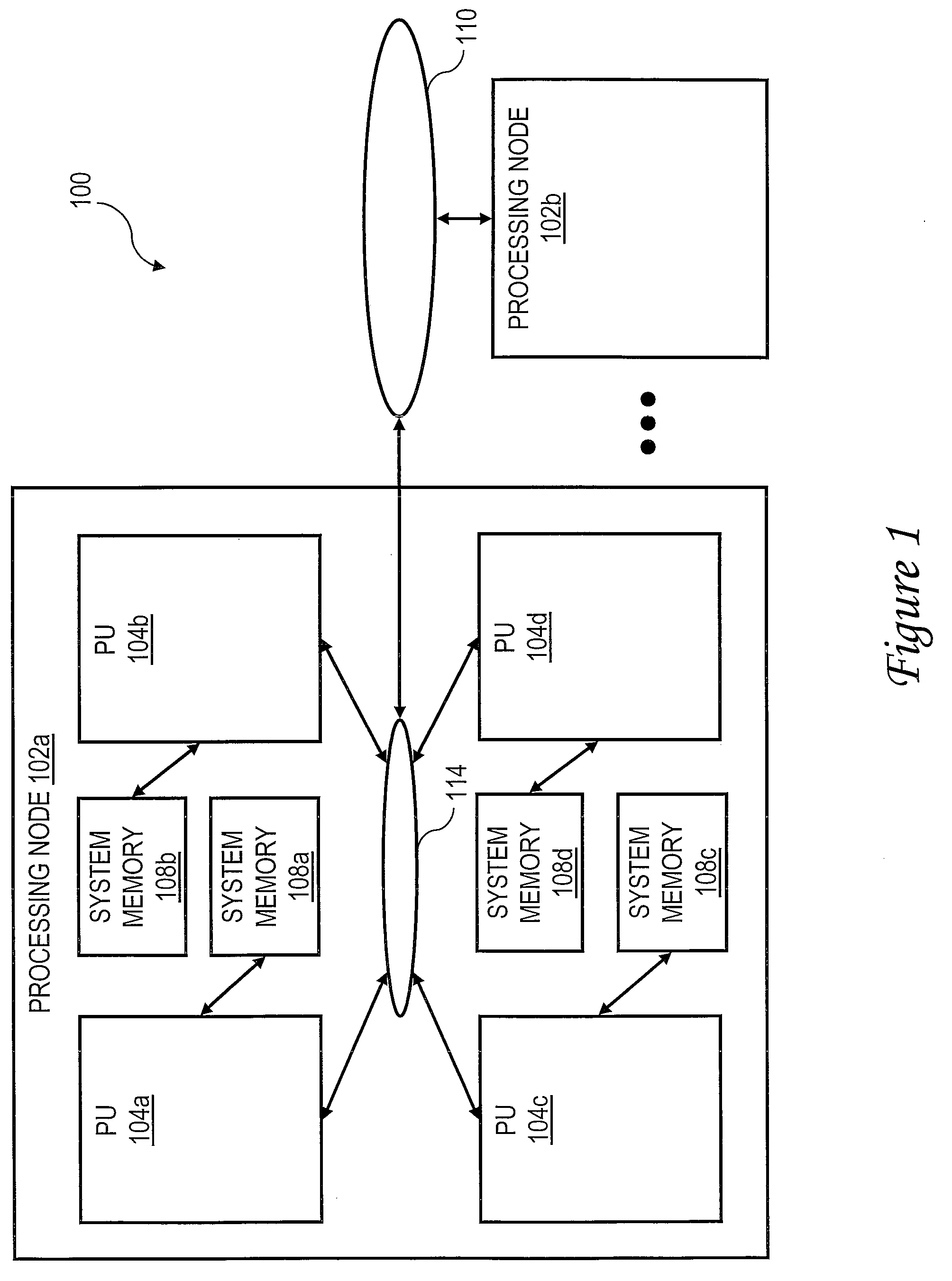
[0022]With reference now to the figures and, in particular, with reference to FIG. 1, there is illustrated a high level block diagram of an exemplary embodiment of a multiprocessor data processing system in accordance with the present invention. As shown, data processing system 100 includes multiple processing nodes 102a, 102b for processing data and instructions. Processing nodes 102a, 102b are coupled to a system interconnect 110 for conveying address, data and control information. System interconnect 110 may be implemented, for example, as a bused interconnect, a switched interconnect or a hybrid interconnect.

[0023]In the depicted embodiment, each processing node 102 is realized as a multi-chip module (MCM) containing four processing units 104a-104d, each preferably realized as a respective integrated circuit. The processing units 104a-104d within each processing node 102 are coupled for communication by a local interconnect 114, which, like system interconnect 110, may be implem...


PUM


Abstract

In response to receiving pre-processed code, a compiler identifies a code section that is not candidate for acceleration and identifying a code block specifying an iterated operation that is a candidate for acceleration. In response to identifying the code section, the compiler generates post-processed code containing one or more lower level instructions corresponding to the identified code section, and in response to identifying the code block, the compiler creates and outputs an operation data structure separate from the post-processed code that identifies the iterated operation. The compiler places a block computation command in the post-processed code that invokes processing of the operation data structure to perform the iterated operation and outputs the post-processed code.

Description

CROSS-REFERENCE[0001]The present application is related to the following co-pending applications, which are incorporated herein by reference in their entireties:[0002](1) U.S. patent application Ser. No. 11 / ______, (Docket No. AUS920070385US1);[0003](2) U.S. patent application Ser. No. 11 / ______, (Docket No. AUS920080285US1);[0004](3) U.S. patent application Ser. No. 11 / ______, (Docket No. AUS920080286US1); and[0005](4) U.S. patent application Ser. No. 11 / ______, (Docket No. AUS920080287US1).BACKGROUND OF THE INVENTION[0006]1. Technical Field[0007]The present invention relates in general to data processing.[0008]2. Description of the Related Art[0009]A number of trends currently influence the development of server-class and mainframe computer systems. In particular, transistor densities within integrated circuits continue to increase according to Moore's Law, which in its current formulation posits that the number of transistors per unit area on integrated circuits will double appro...

Claims


Application Information

Patent Timeline
Patent Type & Authority Applications(United States)
IPC IPC(8): G06F9/45
CPCG06F8/4441
Inventor ARIMILLI, RAVI K.SINHAROY, BALARAM
Owner IBM CORP
Why Eureka
Try Eureka