Fluid Charged Rotary Heating System

a rotary heating system and fluid charge technology, applied in the direction of fluid friction for heating, domestic stoves or ranges, lighting and heating apparatus, etc., can solve the problem of limited maximum effect, achieve high yield, reduce manufacturing and maintenance costs

Inactive Publication Date: 2010-06-24
HARRIS HOWARD +1
View PDF5 Cites 14 Cited by
  • Summary
  • Abstract
  • Description
  • Claims
  • Application Information

AI Technical Summary

Benefits of technology

[0011]According to one aspect of the present invention, heat transfer fluid located between a rotating rotor and stationary housing is heated in a re-circulating fashion in a device which is structurally simple and requires reduced manufacturing and maintenance costs, wherein heat contained in the heat transfer fluid is exchanged with mass in contact with the housing and/or the housing extension.
[0012]It is one object of the present invention to produce a mechanically elegant and thermodynamically highly efficient fluid-charged heating device for increasing pressure and/or temperature of a heat transfer fluid in a closed system comprising mechanically or electrically driven rotor(s) whose surface is provided with continuous helical groove, said groove being also sized and configured to propel the fluid radially outwards in a generally spiral path, until redirected by the interior shape and pressure differences in the housing and housing extensions thereby causing re-circulation of the heat transfer fluid; said rotor rotating in a cyli

Problems solved by technology

A further limitation of the Griggs device is that the maximum effect is limite

Method used


Image

  • Fluid Charged Rotary Heating System
  • Fluid Charged Rotary Heating System
  • Fluid Charged Rotary Heating System

Examples


Embodiment Construction

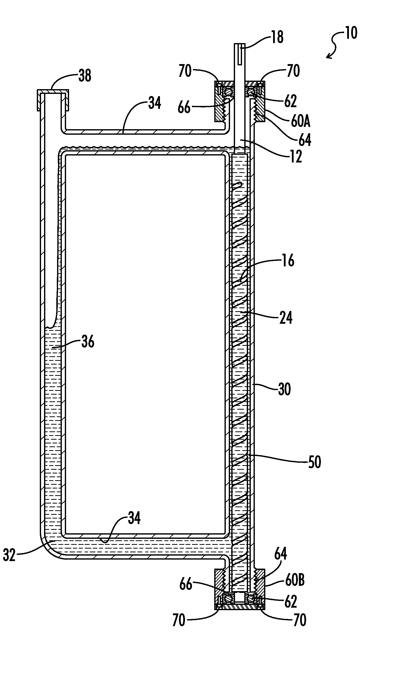
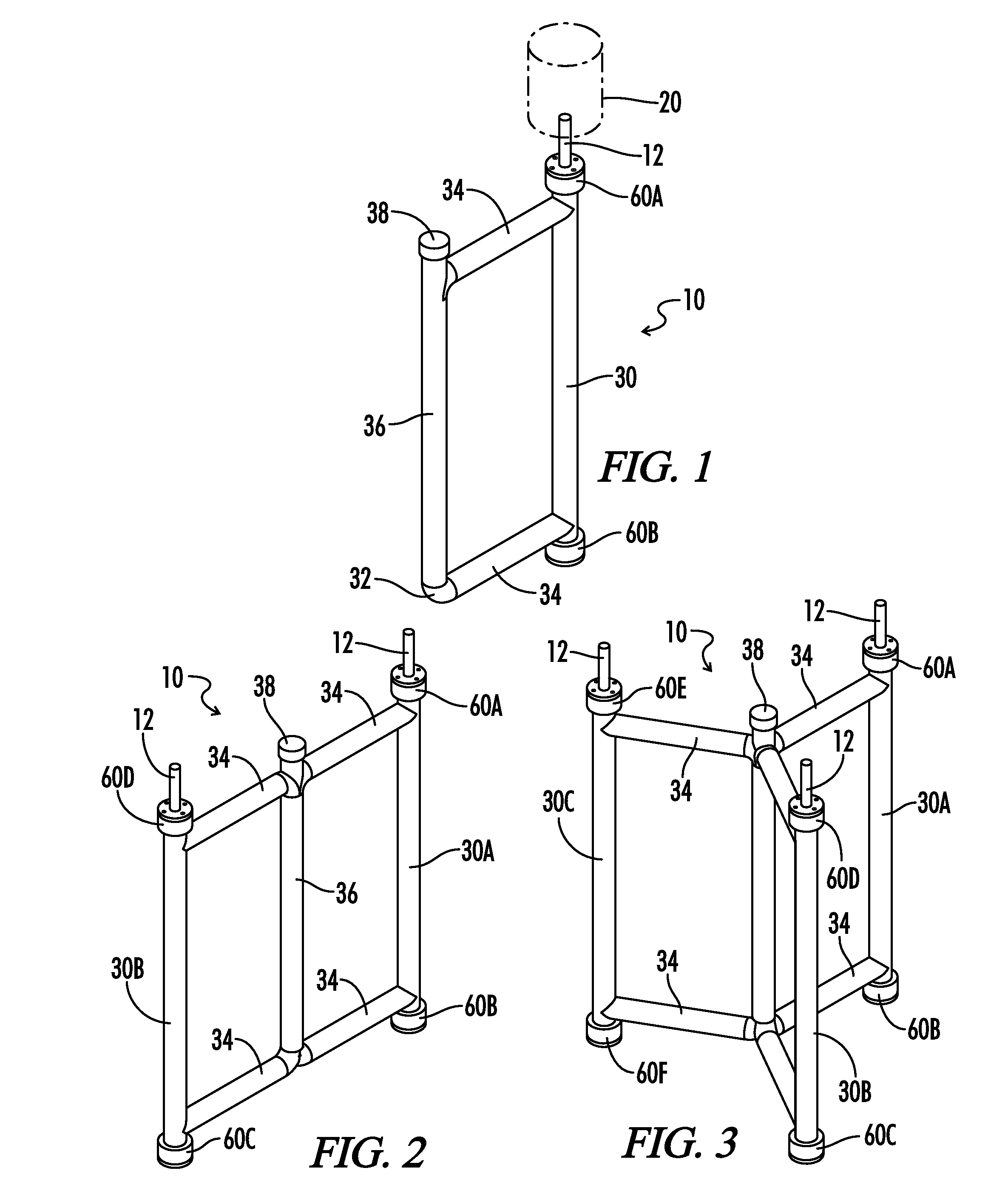
[0026]Referring now to the drawings of the present disclosure in which like numbers represent the same structure in the various views,

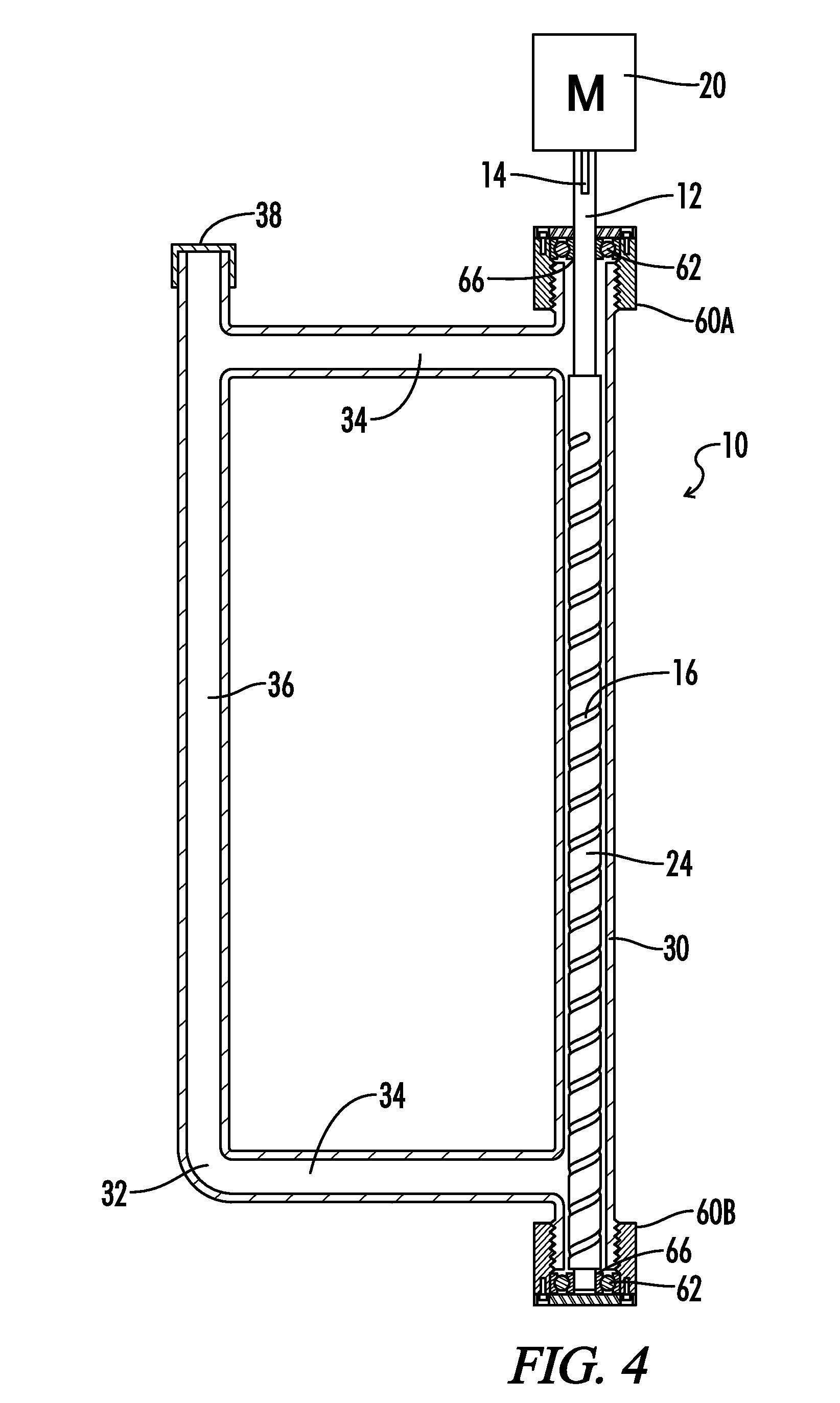
[0027]As shown in FIGS. 1-4, device 10 comprises a rotor 12 mounted on a shaft 14, which rotor 12 rotates within a housing 30 in a recirculating inlet and outlet communication with a housing extension 36 via connecting means 34. Shaft 14 in the embodiment shown in FIG. 4 has a primary diameter of ¼″ and may be formed of forged steel, cast or ductile iron, or other materials as desired. Shaft 14 is designed for rigid interference fit with the shaft bore 18 on the rotor 12. (See FIG. 7). Shaft 14 may be driven by an electric motor 20 or other motive means, and may be driven directly, geared, driven by pulley 26, or driven as otherwise desired. In one embodiment, locking pins, set screws or other fasteners may be used to fix rotor 12 with respect to shaft 14. As used in this specification, shaft 14 encompasses any mechanically suitable connecting means f...


PUM


Abstract

A fluid-charged heating device comprising a cylindrical housing in fluid communication with a housing extension; a cylindrical rotor disposed centrally and mounted for rotation in said cylindrical housing in spaced relation to provide an annular passage for heat transfer fluid to recirculate between the cylindrical housing and the housing extension. The rotor has a surface with a continuous helical groove along the longitudinal axis of the rotor and rotation of the helically grooved rotor causes fluid shearing, heat-generating cavitation, and recirculation of the heat transfer fluid between the housing and the housing extension.

Description

CROSS-REFERENCE TO RELATED APPLICATIONS[0001]This invention claims priority to U.S. Provisional Application 61 / 197,130 filed Oct. 24, 2008.FIELD OF THE INVENTION[0002]The present invention relates generally to rotary heating systems and devices wherein rotating cylindrical rotors are employed to generate heat in heat transfer fluids in contact therewith. Devices of this type can be usefully employed as heating systems in applications requiring hot water supply, for instance in the home, or by incorporation as a heat pump or heating element within a heating system adapted for residential and industrial use.BACKGROUND OF THE INVENTION[0003]Various designs exist for devices which use rotating members to increase pressure and / or temperature of fluids. U.S. Pat. No. 3,791,349 discloses an apparatus and method for production of steam and pressure by creating shock waves in a distended body of water. Various passageways and chambers are employed to create a tortuous path for the fluid and ...

Claims


Application Information

Patent Timeline
IPC IPC(8): F24C9/00F24J3/00
CPCF24J3/003F24C9/00F24V40/00
Inventor HARRIS, HOWARDHARRY, JANE
Owner HARRIS HOWARD
Why Eureka
Try Eureka