Magnetic field detection device

a detection device and magnetic field technology, applied in the direction of galvano-magnetic devices, galvano-magnetic hall-effect devices, instruments, etc., can solve the problems of increasing the detection value reducing the yield of the magnetic field detection device, and greatly affecting the magnetic field, so as to prevent a decrease in yield, increase the sensitivity of the magnetic field detection device, and high-accurate positional relationship

Active Publication Date: 2010-06-24
MITSUBISHI ELECTRIC CORP
View PDF3 Cites 30 Cited by
  • Summary
  • Abstract
  • Description
  • Claims
  • Application Information

AI Technical Summary

Benefits of technology

[0014]According to the magnetic field detection device of the present invention, since the magneto-resistance element is disposed on the outputting portion side while being isolated from the outputting portion, the magneto-resistance element 2 can be applied with the magnetic field stronger than the external magnetic field, whereby the sensitivity of the magnetic field detection device can be increased. Further, since the on-substrate magnetic body is disposed on the same substrate on which the magneto-resistance element is disposed, the on-substrate magnetic body can be disposed while maintaining high-accurate positional relationship with the magneto-resistance element when being formed, for example, using photolithography. As a result, it is possible to prevent a decrease in yield, which results from variations in arrangement position of the on-substrate magnetic body. Still further, in a case where the magneto-resistance element and the on-substrate magnetic body are individually disposed on different main surfaces of the substrate, they can be easily disposed in parallel to the main surfaces of the substrate with a distance determined by a thickness of the substrate. Also in this case, it is possible to prevent a decrease in yield, which results from variations in arrangement position of the on-substrate magnetic body.

Problems solved by technology

However, the magnetic field applied to the magneto-resistance element greatly depends on an arrangement of the magnetic body, which causes a problem that, even in a case where the arrangement of the magnetic body is slightly deviated from an original position, the magnetic field is greatly affected.
Particularly in a case where the magneto-resistance element is downsized or in a case where the magnetic field detection device itself is downsized, there is a problem that an allowance for arrangement deviation of the magnetic body is reduced, and thus an error in detection value of the magnetic field detection device is increased, leading to a decrease in yield when the magnetic field detection device is manufactured.

Method used


Image

  • Magnetic field detection device
  • Magnetic field detection device
  • Magnetic field detection device

Examples


first embodiment

A. First Embodiment

A-1. Device Structure

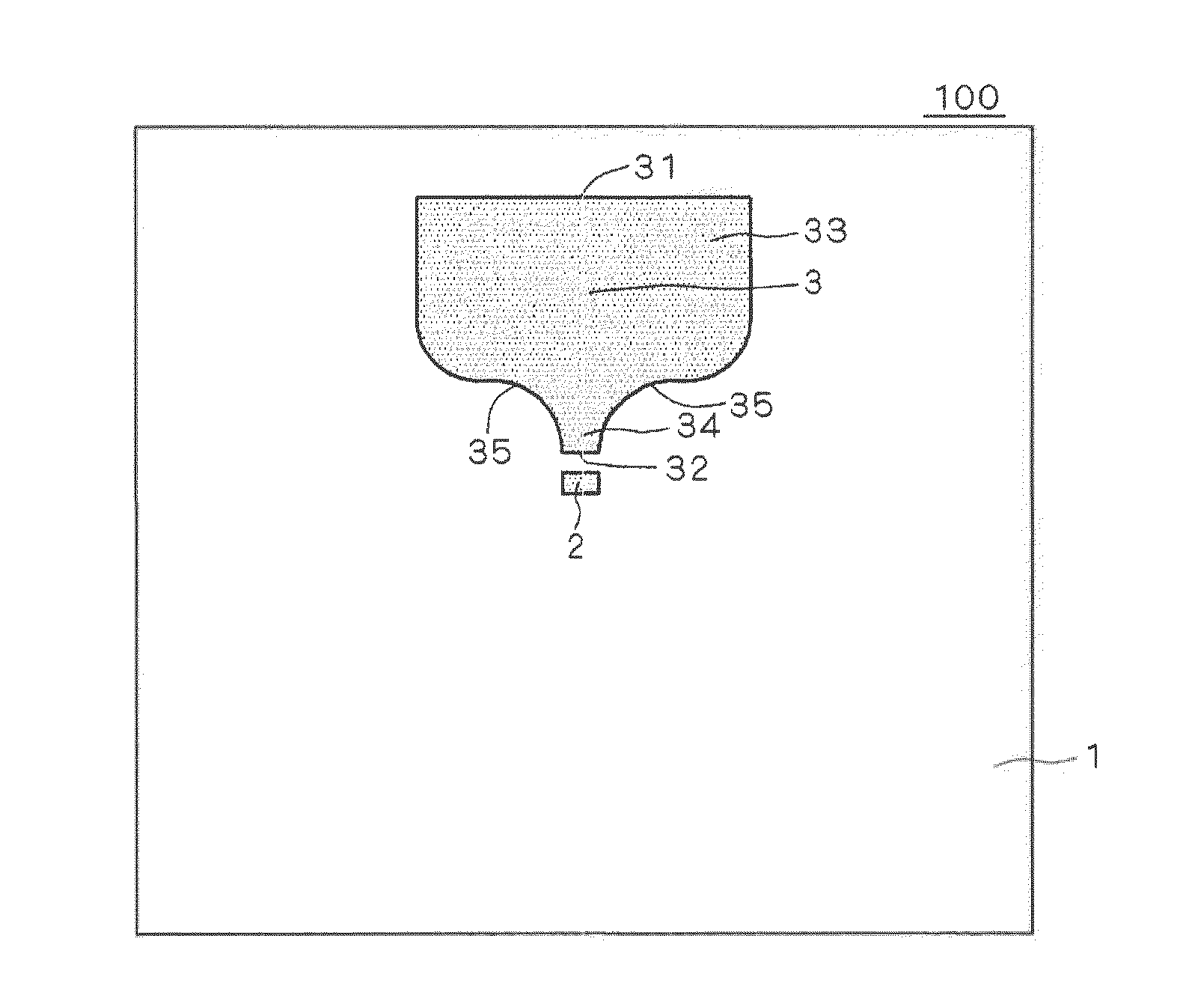
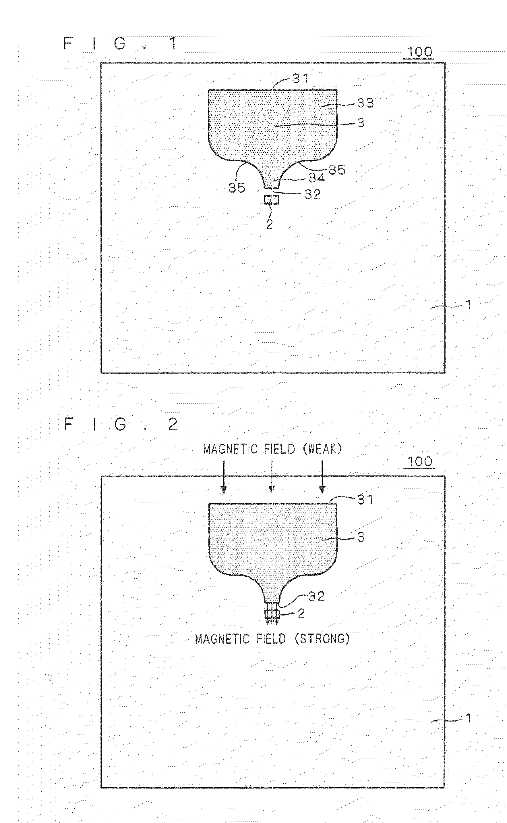
[0033]FIG. 1 shows a structure of a magnetic field detection device 100 according to a first embodiment of the present invention. FIG. 1 is a plan view of a substrate 1, in which a magneto-resistance element 2 and an on-substrate magnetic body 3 which form the magnetic field detection device 100 are disposed, viewed from above a main surface thereof.

[0034]As shown in FIG. 1, a shape of the on-substrate magnetic body 3 in plan view is a tapered shape on one end portion (referred to as output-side end portion) 32 side and is a substantially funnel shape in which the other end portion (referred to as input-side end portion) 31 is larger in width than the one end on the other end portion side opposite to the one end portion. The magneto-resistance element 2 is disposed in front of the output-side end portion.

[0035]The reason why the shape of the on-substrate magnetic body 3 is referred to as the substantially funnel shape is that a contour of a ta...

second embodiment

B. Second Embodiment

B-1. Device Structure

[0077]FIG. 5 shows a structure of a magnetic field detection device 200 according to a second embodiment of the present invention. The magnetic field detection device 100 according to the first embodiment, which is shown in FIG. 1, has the structure in which the magneto-resistance element 2 and the on-substrate magnetic body 3 are disposed on the main surface of the substrate 1. On the other hand, the magnetic field detection device 200 has a structure which further includes externally-mounted magnetic bodies 8 each extending in a direction perpendicular to main surfaces of on-substrate magnetic bodies 30 disposed on a substrate 10.

[0078]That is, the magnetic field detection device 200 shown in FIG. 5 includes: three on-substrate magnetic bodies 30 which are arranged in a direction of a side of the substrate 10 and are independent from each other; three externally-mounted magnetic bodies 8 each extending in the direction perpendicular to the ...

third embodiment

C. Third Embodiment

C-1. Device Structure

[0115]FIG. 11 shows a structure of a magnetic field detection device 300 according to a third embodiment of the present invention. The magnetic field detection device 100 according to the first embodiment, which is shown in FIG. 1, has the structure in which the magneto-resistance element 2 and the on-substrate magnetic body 3 are disposed on the main surface of the substrate 1. On the other hand, the magnetic field detection device 300 has a structure which further includes two plate-like externally-mounted magnetic bodies 8A individually extending in a direction perpendicular to main surfaces of two on-substrate magnetic bodies 30A disposed on the substrate 10, and a permanent magnet 6 which magnetically couples the two externally-mounted magnetic bodies 8A. The externally-mounted magnetic bodies 8A and the permanent magnet 6 form an external magnetic circuit 5A. Note that the permanent magnet 6 is magnetized so that surfaces thereof being i...


PUM


Abstract

A magnetic field detection device including a magnetic body (magnetic flux guide) provided for adjusting a magnetic field to be applied to a magneto-resistance element. A shape of an on-substrate magnetic body in plan view is a tapered shape on one end portion side and a substantially funnel shape on another end portion side opposite the one end portion, the another end portion being larger in width than the one end portion, and a magneto-resistance element is disposed in front of an output-side end portion. In the on-substrate magnetic body, a contour of a tapered portion is not linear like a funnel, but has a curved shape in which a first curved portion protruding outward with a gentle curvature and a second curved portion protruding inward with a curvature similar to that of the first curved portion are continuously formed.

Description

TECHNICAL FIELD[0001]The present invention relates to a magnetic field detection device, and more particularly, to a magnetic field detection device using a magneto-resistance element.BACKGROUND ART[0002]In a magnetic field detection device which outputs a detection signal corresponding to a magnetic field (external magnetic field) applied from an outside thereof, there is known, as a detecting element, a magneto-resistance element using a magneto-resistance effect of a magnetic material in addition to a Hall element using a Hall effect of a semiconductor. As the magneto-resistance element, there are known an anisotropic magneto-resistance (AMR) element using an anisotropic magneto-resistance effect of metal, a giant magneto-resistance (GMR) element using a giant magneto-resistance effect, a tunnel magneto-resistance (TMR) effect using a tunnel magneto-resistance effect, and the like. An SN ratio of the magnetic field detection device is improved as an output of a magnetic field det...

Claims


Application Information

Patent Timeline
Patent Type & Authority Applications(United States)
IPC IPC(8): G01R33/02
CPCB82Y25/00G01R33/093G01R33/091G01R33/072
Inventor FURUKAWA, TAISUKEKUROIWA, TAKEHARUTOMOHISA, SHINGOTAKENAGA, TAKASHITAKI, MASAKAZUTAKADA, HIROSHIABE, YUJI
Owner MITSUBISHI ELECTRIC CORP
Why Eureka
Try Eureka