Film bulk acoustic resonator

a resonator and film technology, applied in piezoelectric/electrostrictive/magnetostrictive devices, piezoelectric/electrostriction/magnetostriction machines, electrical apparatus, etc., can solve the problem of difficult to obtain the optimal solution of the planar shape, unnecessarily large insertion loss, spurious noise in the resonant characteristics, etc. problem, to achieve the effect of suppressing the generation of a standing wav

Inactive Publication Date: 2010-06-24
SONY CORP
View PDF13 Cites 11 Cited by
  • Summary
  • Abstract
  • Description
  • Claims
  • Application Information

AI Technical Summary

Benefits of technology

[0011]Since the planar shape of the resonant portion is configured as described above, a generation path for generating a standing wave to be caused by a transverse-mode acoustic wave induced within the resonant portion and reflected by an outer peripheral wall is reduced. For example, by intersecting a straight line along which a part of the ellipse is cut off with at least one of a minor axis and a major axis of the ellipse, at least one of generation paths for standing waves along the minor axis and the major axis can be reduced. Thus, generation of a standing wave to be caused by a transverse-mode acoustic wave can be suppressed. Furthermore, since the planar shape of the resonant portion is a shape that is a cut ellipse, calculation of the area of the resonant portion, that is, the capacitance of the resonator, can be easily performed.
[0012]As described above, according to the film bulk acoustic resonator of the present invention, with a simple configuration in which the planar shape of the resonant portion is a shape that is an ellipse having a part thereof cut off, generation of a standing wave to be caused by a transverse-mode acoustic wave can be suppressed. Thus, even with easy design, an improvement in resonant characteristics can be achieved. In addition, a reduction in the insertion loss in a band-pass filter using such a film bulk acoustic resonator can be achieved.

Problems solved by technology

More specifically, since transverse-mode acoustic waves propagate a long distance compared with longitudinal-mode acoustic waves, the frequency of a transverse-mode acoustic wave is significantly lower than the frequency of a longitudinal-mode acoustic wave (that is, a resonance frequency γ), and a higher harmonic wave component of a transverse-mode acoustic wave may have a frequency in the vicinity of the resonance frequency γ. Thus, noise called spurious occurs in the resonant characteristics of such a film bulk acoustic resonator.
If the above-described band-pass filter is formed using such a film bulk acoustic resonator, a ripple occurs in a pass frequency band, thus causing an unnecessarily large insertion loss.
Thus, it is difficult to obtain the optimal solution of the planar shape.
It is necessary to obtain the optimal solution of the planar shape such that the resonant portion has a predetermined area, and the involved operation is complicated.
This does not achieve a sufficient effect of reducing the generation of standing waves.

Method used


Image

  • Film bulk acoustic resonator
  • Film bulk acoustic resonator
  • Film bulk acoustic resonator

Examples


first embodiment

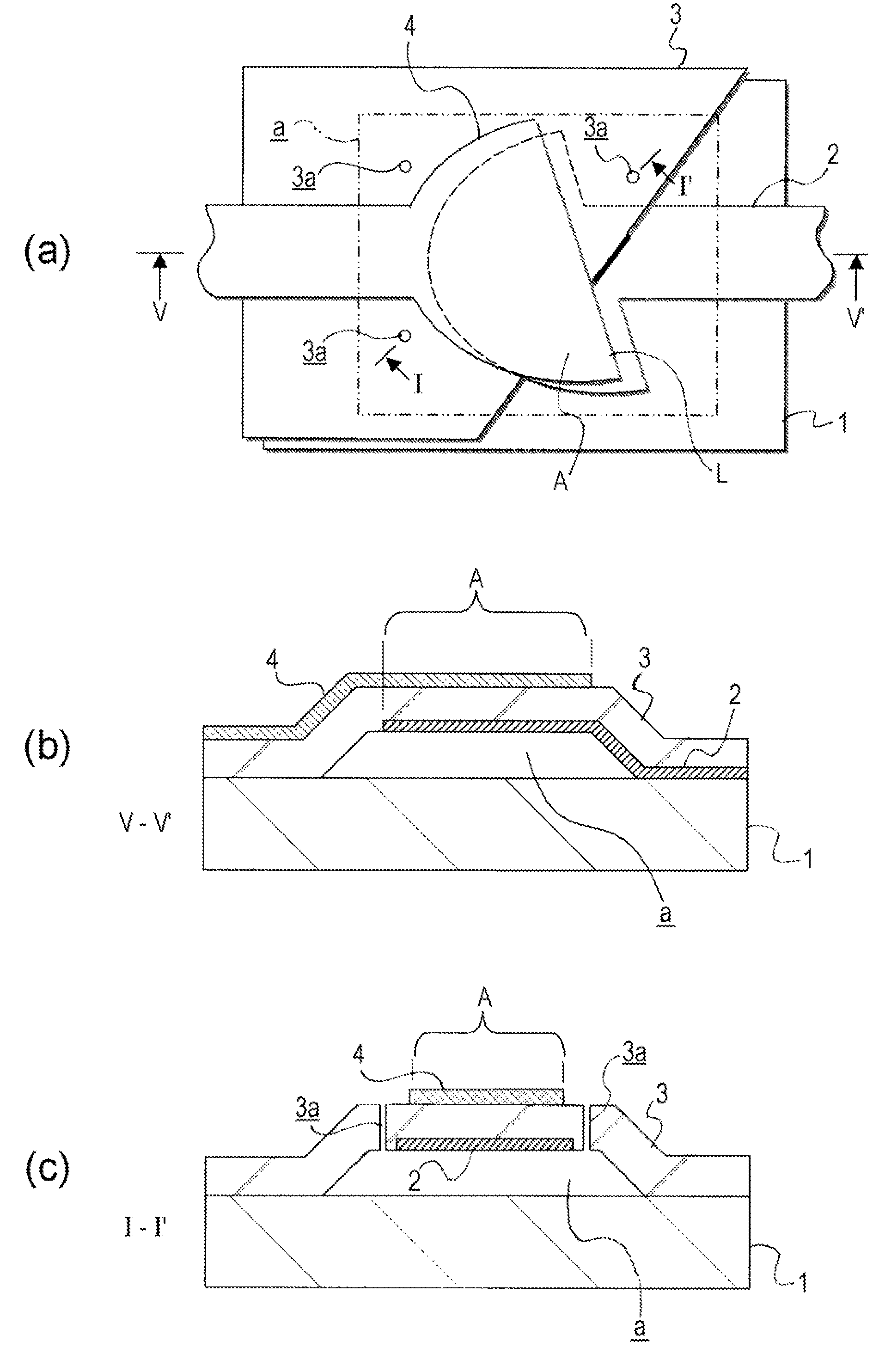
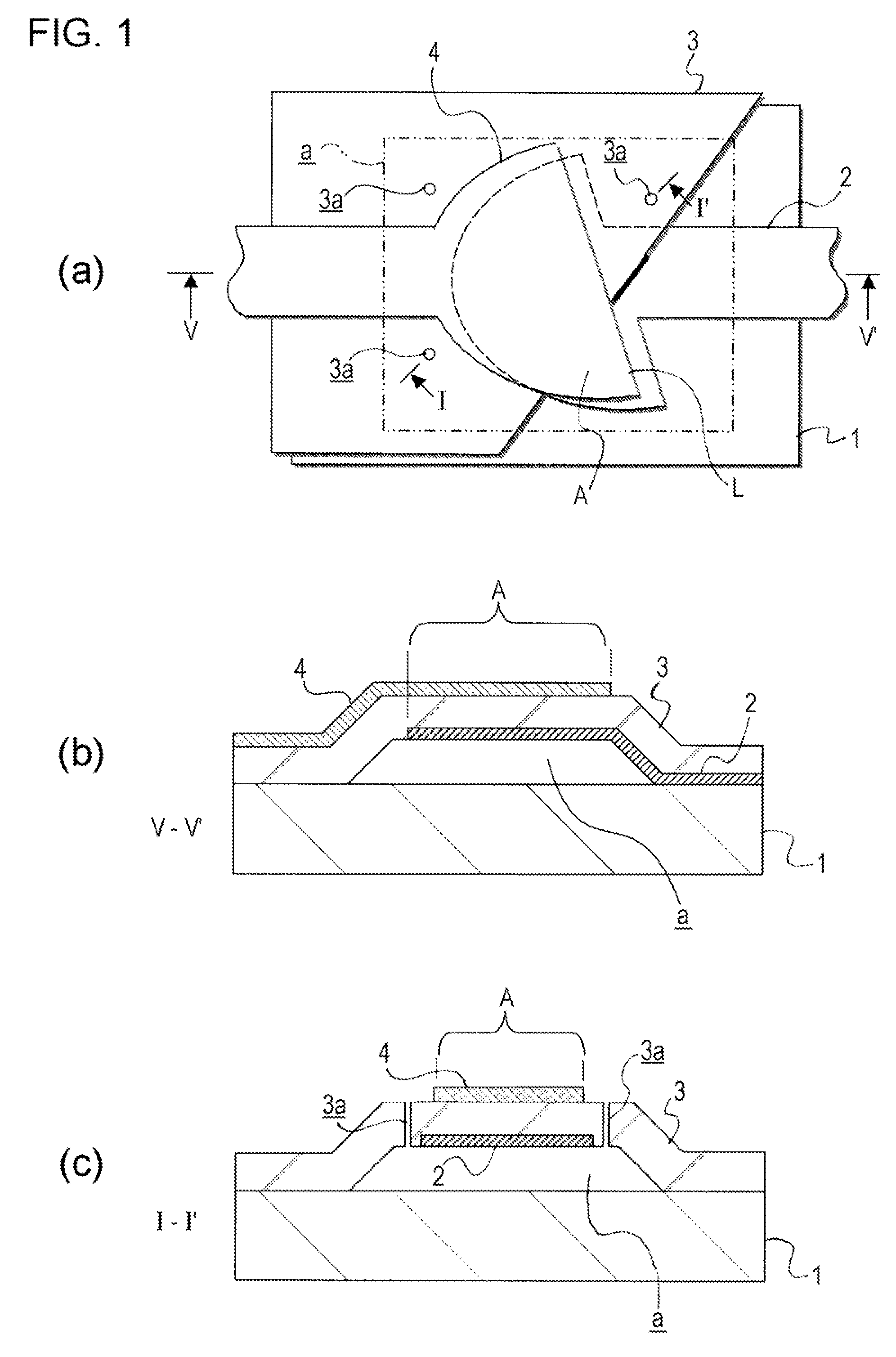
[0023]Part (a) of FIG. 1 is a plan view of a film bulk acoustic resonator according to a first embodiment. For convenience of explanation, in part (a) of FIG. 1, the piezoelectric material layer 3 a part of which is cut off is illustrated. Part (b) of FIG. 1 is a V-V′ sectional view of the plan view, and part (c) of FIG. 1 is an I-I′ sectional view of the plan view. Here, in FIG. 1, parts corresponding to those in FIG. 7, which is used for the description of the background art, are represented by the same symbols.

[0024]The film bulk acoustic resonator shown in the drawings includes a resonant portion A formed by stacking a first electrode 2, a piezoelectric material layer 3, and a second electrode 4 in that order above a substrate 1 with an air space a therebetween. In addition, in this embodiment, the planar shape of the resonant portion A, that is, the shape viewed in a thickness direction in a case where the second electrode 4, the piezoelectric material layer 3, and the first el...

second embodiment

[0053]Part (a) of FIG. 6 is a plan view of a film bulk acoustic resonator according to a second embodiment, part (b) of FIG. 6 is a V-V′ sectional view of the plan view, and part (c) of FIG. 6 is an I-I′ sectional view of the plan view.

[0054]The film bulk acoustic resonator shown in the drawings is different from the film bulk acoustic resonators explained with reference to FIGS. 1 to 4 in that a hole part 4a that extends to the piezoelectric material layer 3 is provided in a portion of the second electrode 4 of the resonant portion A. The other features of the configuration of the film bulk acoustic resonator shown in the drawings are similar to those of the film bulk acoustic resonators explained with reference to FIGS. 1 to 4.

[0055]That is, as explained in the first embodiment, the resonant portion A of the film bulk acoustic resonator according to the second embodiment is configured to have a planar shape that is an ellipse having a part thereof cut off. In addition, in the reso...


PUM


Abstract

An object is to provide a film bulk acoustic resonator capable of improving resonant characteristics by reducing the generation of a standing wave to be caused by a transverse-mode acoustic wave to a minimum. In a film bulk acoustic resonator including a resonant portion A having a piezoelectric material layer 3 sandwiched between a first electrode 2 and a second electrode 4, the resonant portion A is configured to have a planar shape that is an ellipse having a part thereof cut off along a straight line L. The straight line L intersects at least one of a minor axis and a major axis of the ellipse, and preferably intersects both the minor axis and the major axis, and passes through the center of the ellipse.

Description

TECHNICAL FIELD[0001]The present invention relates to a film bulk acoustic resonator that can be suitably used for a small-sized high-frequency filter to be used in a communication device.BACKGROUND ART[0002]In recent years, due to improvements in functions and speeding up of communication devices, such as cellular phones and PDA (personal digital assistant: personal portable information communication) devices, further miniaturization and reduction in cost have been required for internal high-frequency filters operating at a frequency from several hundred MHz to several GHz. As promising candidates that meet such requirements, band-pass filters in which film bulk acoustic resonators (Film Bulk Acoustic Resonators: FBARs) are arranged in a ladder form and through which only electric signals in a desired frequency band pass with low loss are available. This is because, since film bulk acoustic resonators are formed by application of a semiconductor manufacturing technology, reductions...

Claims


Application Information

Patent Timeline
Patent Type & Authority Applications(United States)
IPC IPC(8): H03H9/15
CPCH03H9/02102H03H9/02118H03H9/173H03H9/132H03H9/02133
Inventor OKA, SHUICHIOHNO, TERUKAZU
Owner SONY CORP
Why Eureka
Try Eureka