Fixation of a spiral spring in a watch movement

a technology of spiral springs and watch movements, which is applied in the direction of regulating apparatus, clock driving mechanisms, instruments, etc., can solve the problems of increasing the proportion of unusable parts, increasing the cost of manufacturing governing parts, and so as to simplify the adjustment steps to some extent. , the effect of increasing the proportion of springs

Inactive Publication Date: 2010-06-24
MFG ROGER DUBUIS
View PDF6 Cites 26 Cited by
  • Summary
  • Abstract
  • Description
  • Claims
  • Application Information

AI Technical Summary

Benefits of technology

[0014]The present invention provides a method for fixing a spring into a balance-wheel-and-spring assembly whereby the limitations of the prior art are overcome, among other things by increasing the proportion of springs that can be used, thereby partly offsetting manufacturing defects, and by simplifying to some extent the adjustment steps necessary during and after fixings.
[0015]It is another object of the invention to provide a method for making an isochronous balance-wheel-and-spring assembly in which one spring out of a series of springs is paired with a balance wheel. The spring has characteristics that vary by comparison with other springs of the series, and the spring is designed to be mounted on the staff of the balance wheel via a collet. One collet is selected from a set of collets of different sizes on the basis of the spring's characteristics. The collets of different sizes have connection points for attachment of the spring that are located (after assembly) at different distances from the center of the staff of the balance wheel, and the choice of the collet of the most appropriate size facilitates the adjustment of the balance-wheel-and-spring assembly.
[0016]In particular, the choice of the collet of the most appropriate size avoids stress on the inner end of the spring. This safeguards the angle of the point of attachment of this spring to the collet and, at the same time, ensures that the origin of the spring does not move away from the center of the balance staff, and also ensures that the spring leaves the collet tangentially.

Problems solved by technology

Manufacture of the governing part is generally costly, and maintaining a constant quality is a major challenge.
Clearly, the greater the number of classes of springs and balance wheels, the more difficult and laborious it becomes to pair them up and the more the proportion of unusable parts rises.
This operation similarly requires a high level of manual intervention and many defective parts have to be thrown away.
However, in reality, as already indicated, each spring has defects of manufacture, and even when one class of springs is paired with one class of balance wheels, it is still difficult to satisfy each of the above requirements for all springs of a given class.
As a result, a large proportion of springs in a given series are still unusable.

Method used


Image

  • Fixation of a spiral spring in a watch movement
  • Fixation of a spiral spring in a watch movement
  • Fixation of a spiral spring in a watch movement

Examples


Embodiment Construction

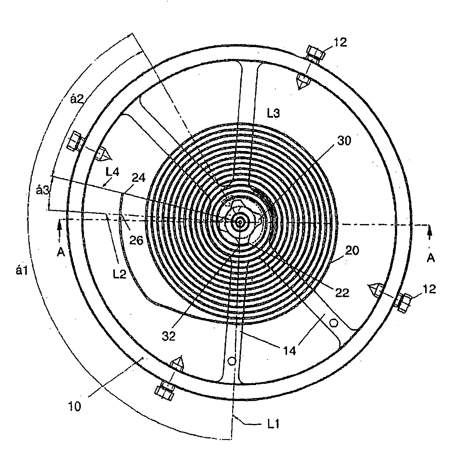
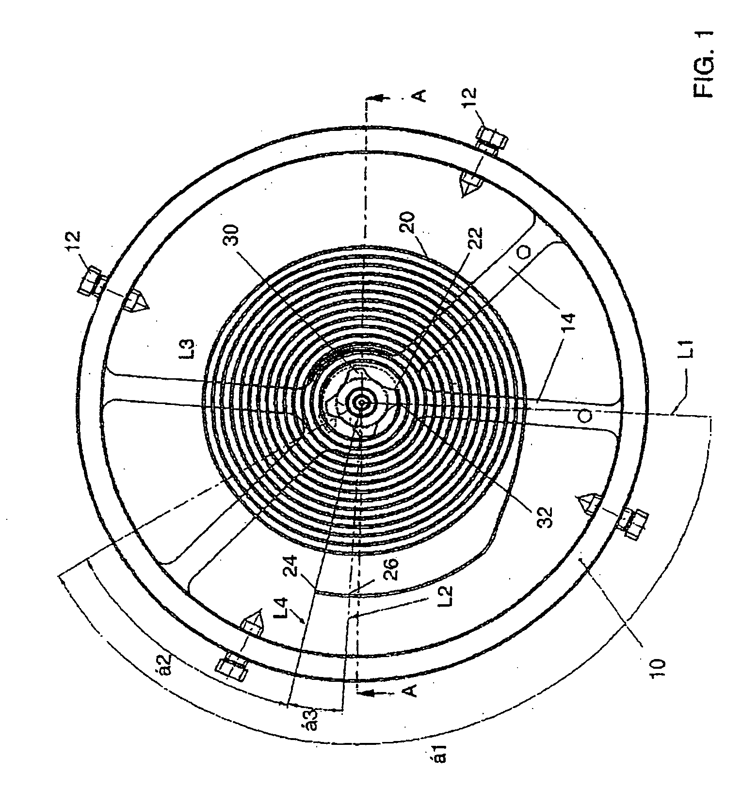
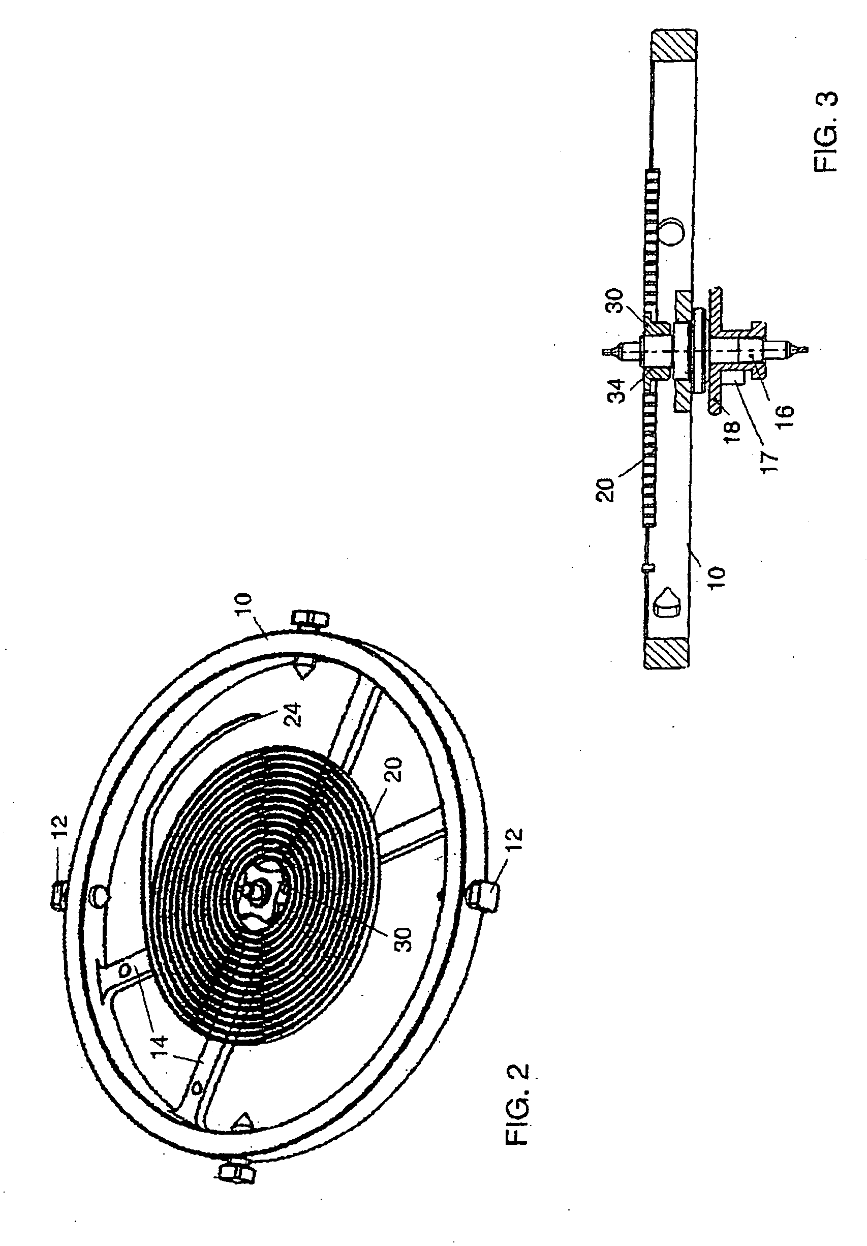
[0027]A conventional balance-wheel-and-spring assembly is shown in FIGS. 1-3. It comprises a balance wheel 10 which in this example has a number of adjustment screws 12 and arms 14. The position, number and even the presence of the screws 12 may vary depending on the type of balance wheel. A roller 18 (in this case a double roller) is mounted on the balance staff 16 and carries a pin 17 which receives the impulses from an escapement anchor (not shown). The spring 20 has an innermost coil which ends in an inner end 22, and an outermost coil which ends in an outer end 24. As explained below, the spring 20 is mounted on the staff 16 via a collet 30. Specifically, the spring is fixed towards its inner end 22 to a connection point 32 on the collet. At a point 26 towards its outer end 24, the spring is fixed to the bridge of the balance wheel (not shown) by a stud (also not shown).

[0028]In general terms, the balance wheel 10 and the spring 20 can each be made from a variety of materials a...


PUM

PropertyMeasurementUnit
sizesaaaaaaaaaa
sizesaaaaaaaaaa
sizesaaaaaaaaaa

Abstract

A method is disclosed for making an isochronous balance-wheel-and-spring assembly for a horological movement in which one spring out of a series of springs is paired with a balance wheel. The spring has characteristics that vary by comparison with other springs of the series, and the spring is designed to be mounted on the staff of the balance-wheel via a collet. One collet out of a set of collets of different sizes is selected on the basis of the spring's characteristics. The collets of different sizes have connection points for attachment of the spring that are located (after assembly) at different distances from the center of the balance staff, the choice of the collet of the most appropriate size facilitating the adjustment of the balance-wheel-and-spring assembly.

Description

TECHNICAL FIELD[0001]The present invention relates to a method for fixing a spring for a mechanical balance-wheel-and-spring oscillator for a horological movement which, in particular, simplifies the. necessary steps of adjustment during and after the fixing despite the presence of defects and / or variations in the spring resulting from its manufacture.Prior Art[0002]The governor of a mechanical watch is conventionally an inertial flywheel known as the balance wheel, with a spiral-wound spring known as the spring or balance spring. This balance-wheel-and-spring assembly is at the heart of the governing assembly of a mechanical horological movement. Nowadays, the balance spring used in mechanical watch movements is usually a metallic spring strip such as an Fe—Ni based alloy of rectangular section, wound up on itself into an Archimedean spiral of from 12 to 15 coils.[0003]The inner end of the spring is conventionally fixed to the balance staff by means of a collet. Various different f...

Claims


Application Information

Patent Timeline
Patent Type & Authority Applications(United States)
IPC IPC(8): G04B15/00B23P17/00G04B17/04
CPCG04B17/06Y10T29/49G04D7/10G04D7/08
Inventor SILVA, SERGIO
Owner MFG ROGER DUBUIS
Why Eureka
Try Eureka