

Development roller, development device, processing cartridge and image forming device
- Summary
- Abstract
- Description
- Claims
- Application Information
AI Technical Summary
Benefits of technology
Problems solved by technology
Method used
Image

Examples
first embodiment
[0091]the present invention is described with reference to FIGS. 1 to 4 as follows.
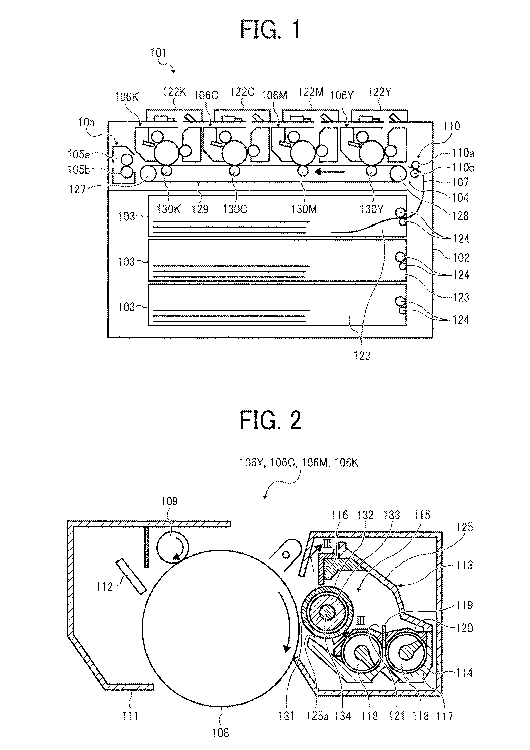
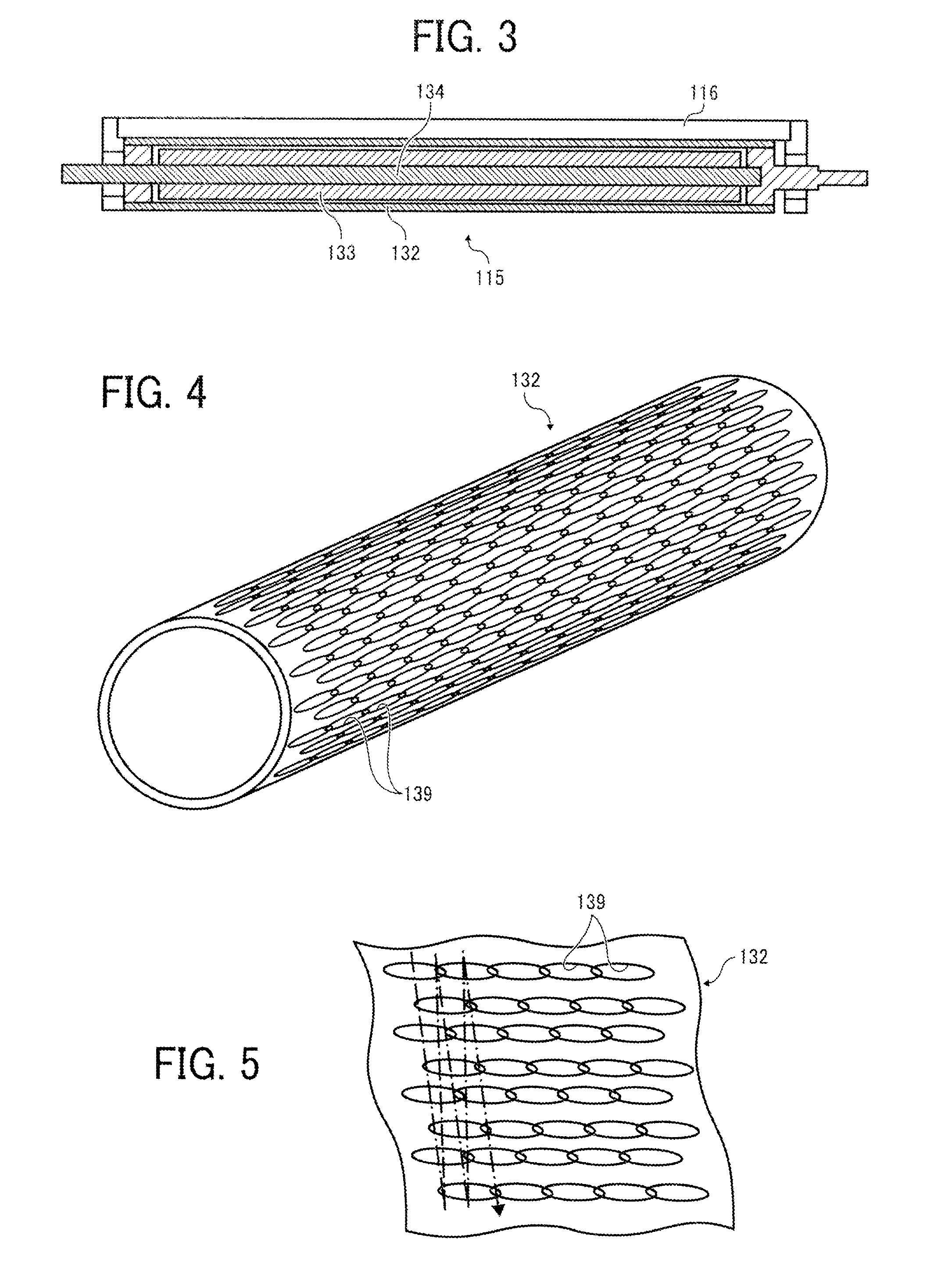
[0092]FIG. 1 is a sectional view showing a main part of an image forming apparatus according to the first embodiment of the present invention. FIG. 2 is a sectional view showing a development device of the image forming apparatus shown in FIG. 1 according to the first embodiment of the present invention. FIG. 3 is a sectional view as viewed along a line III-III of FIG. 2. FIG. 4 is an explanatory view showing an operating state of the development device shown in FIG. 2.
[0093]The image forming apparatus 201 forms an image of each color of yellow (Y), magenta (M), cyan (C), black (K), that is to say, a color image on a recording paper 207 (see FIG. 8) as a transfer member. Here, each unit corresponding to the color of yellow, magenta, cyan, black is shown with Y, N, C, K suffixed to the reference number.
[0094]The image forming apparatus 101 includes at least a main body 102, a paper supplying unit 103, ...
second embodiment
[0181]Next, the present invention will be described with reference to FIGS. 15 to 19.
[0182]Parts equivalent to the first embodiment described above are denoted by the same reference numerals.
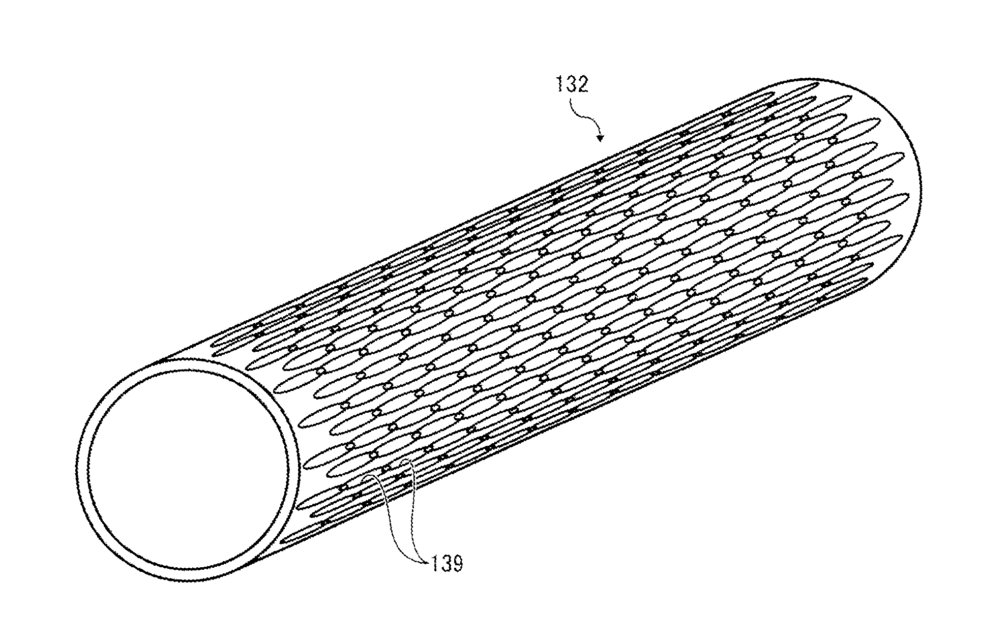
[0183]In the developing sleeve 132 in the embodiment of the present invention as shown in FIG. 15, similar to the above-described first embodiment, the depressions 139 formed on the external surface of the developing sleeve 132 each having an oval shape viewed from the top are formed so that the longitudinal direction thereof is formed along the longitudinal direction of the developing sleeve 132 and in a slightly curved oval shape. The depressions 139 are arranged side by side along the spiral curve on the external surface of the developing sleeve 132 as shown in dot-dash lines in FIG. 16.
[0184]Further, as shown in FIGS. 16 and 17A, a large number (plurality) of the depressions 139 described above are arranged in a regular manner so that the ends of the two depressions which are adjacent with e...
PUM
 Abstract
Description
Claims
Application Information