
Method and system for robotic algae harvest

Inactive Publication Date: 2010-06-24
ROBOTIC RES OPCO LLC
View PDF5 Cites 23 Cited by
  • Summary
  • Abstract
  • Description
  • Claims
  • Application Information

AI Technical Summary

Benefits of technology

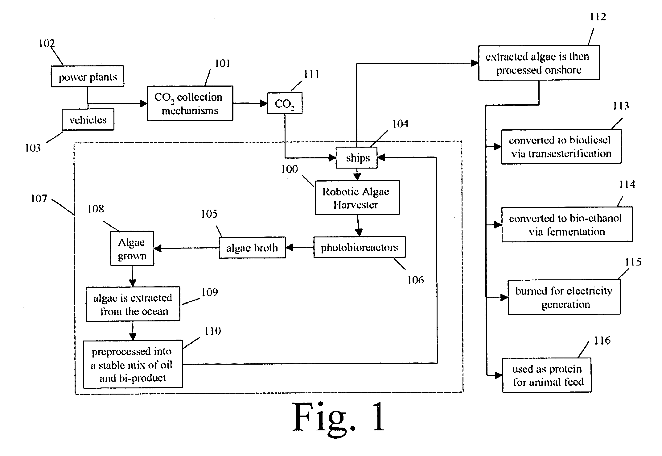
[0013]The proposed system referred to herein as the Robotic Algae Harvester (also referred to as “RAH”) is composed of an ocean floating robotic system that provides a set of enclosed volume photobioreactions (PBR) for algae growth. Some of the advantages of the proposed system include: Absorption of CO2 with the production of biodiesel; the sea provides ample heat dissipation maintaining the water at optimal growth temperatures; an abundant water supply; enclosed growth environment that allows growth of oil rich algae varieties; enclosed growth environment that provides advantages for high rates of CO2 enrichment; no real estate costs as the robotic platform will be floating in the ocean; maximum photosynthetically active radiation (PAR) by strategically locating the systems in areas where the 400-700 nm part of the spectrum is the strongest and has the least to no environmental impact as RAH will be floating far away from coastal areas; and high endurance to storms as RAH will sink below surface to avoid rough weather.
[0016]It is also therefore an objective of the present invention to teach the use of algae that will not have adverse effects on food prices, nor result in a ‘bio-fuel carbon debt’ unlike bio-fuels products based on food products.

Problems solved by technology

The major hurdles with microalgae harvesting include: Algae varieties rich in oils do not survive well in open ponds because the have a hard time competing with naturally occurring algae; Optimal algae grows is dependent on the temperature of the water; Algae cultures require large amounts of water; and Dissolving sufficient amounts of CO2 from the air require large air-water surfaces.
The recent interest in the use of agriculture products as replacements for petrochemical products (biodegradable plastics, ethanol for transportation, etc) has had unintended consequences (rise in food prices) and unseen environmental impact (carbon emissions).

Method used


Image

  • Method and system for robotic algae harvest
  • Method and system for robotic algae harvest
  • Method and system for robotic algae harvest

Examples


Embodiment Construction

[0025]In the following detailed description of the invention of exemplary embodiments of the invention, reference is made to the accompanying drawings (where like numbers represent like elements), which form a part hereof, and in which is shown by way of illustration specific exemplary embodiments in which the invention may be practiced. These embodiments are described in sufficient detail to enable those skilled in the art to practice the invention, but other embodiments may be utilized and logical, mechanical, electrical, and other changes may be made without departing from the scope of the present invention. The following detailed description is, therefore, not to be taken in a limiting sense, and the scope of the present invention is defined only by the appended claims.

[0026]In the following description, numerous specific details are set forth to provide a thorough understanding of the invention. However, it is understood that the invention may be practiced without these specifi...


PUM


Abstract

A Robotic Algae Harvester (RAH) of the present invention works by providing a CO2 collection mechanism that is installed in power plants or vehicles. These systems are available using current technology and have been proven to be scalable. CO2 is then transported to RAH using ships. The RAH will feed and re-circulate algae broth through the photobioreactors (PBRs). The PBRs float in the ocean while the algae through photosynthesis will transform the CO2 into biomass in a continuous process. The extracted algae will processed into a stable mix of oil and bi-product and transferred to the ship that brought the CO2. The algae is then processed onshore in some of the following manners: converted to biodiesel via transesterification; converted to bio-ethanol via fermentation; burned for electricity generation; and / or used as protein for animal feed or food products.

Description

FEDERALLY SPONSORED RESEARCH[0001]Not ApplicableSEQUENCE LISTING OR PROGRAM[0002]Not ApplicableCROSS REFERENCE TO RELATED APPLICATIONS[0003]Not ApplicableTECHNICAL FIELD OF THE INVENTION[0004]The present invention relates generally to a method and system for growing and harvesting algae for use in bio-fuels. More specifically, the present invention relates to a method and system for robotic algae harvest for use in bio-fuels and other applications.BACKGROUND OF THE INVENTION[0005]There are two challenges facing our society that could menace our standards of living and way of life. The first is carbon emissions from our cars and power plants are contributing to global warming and could in the long term threaten landmasses by raising water levels. The second is fuel prices are forcing many industries out of business, as well as putting pressure on the average citizens on their daily work. Current fuel prices produce a drag on the U.S. economy and create large cash surpluses in sometim...

Claims


Application Information

Patent Timeline
IPC IPC(8): C12M1/00C12N1/12C12P7/06
CPCA01G33/00C12M21/02C12M23/06C12M23/44C12M23/56C12M33/00Y02E50/17C12M43/08C12N1/12C12P7/6463C12P7/649Y02E50/13C12M43/02Y02A40/80Y02E50/10Y02P20/133Y02P60/20
Inventor LACAZE, ALBERTO DANIELMURPHY, KARL NICHOLAS
Owner ROBOTIC RES OPCO LLC
Learn More