Rotational intravascular ultrasound probe and method of manufacturing the same

Active Publication Date: 2010-06-24
VOLCANO CORP
View PDF18 Cites 98 Cited by
  • Summary
  • Abstract
  • Description
  • Claims
  • Application Information

AI Technical Summary

Problems solved by technology

The preformed metallic housing can negatively impact image quality because it is constructed of a strongly reflective and resonant material.
In addition, the transducer subassembly and transducer housing are usually

Method used


Image

  • Rotational intravascular ultrasound probe and method of manufacturing the same
  • Rotational intravascular ultrasound probe and method of manufacturing the same
  • Rotational intravascular ultrasound probe and method of manufacturing the same

Examples


Embodiment Construction

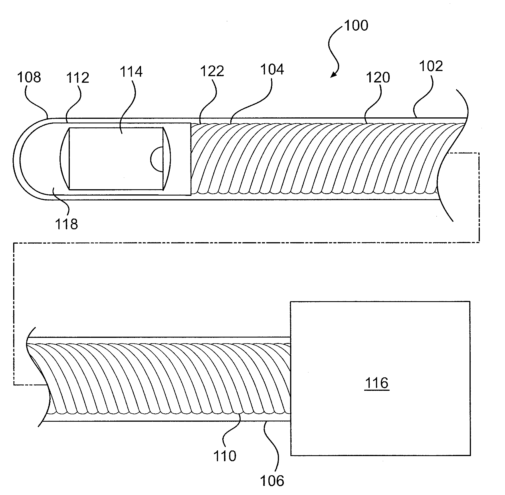
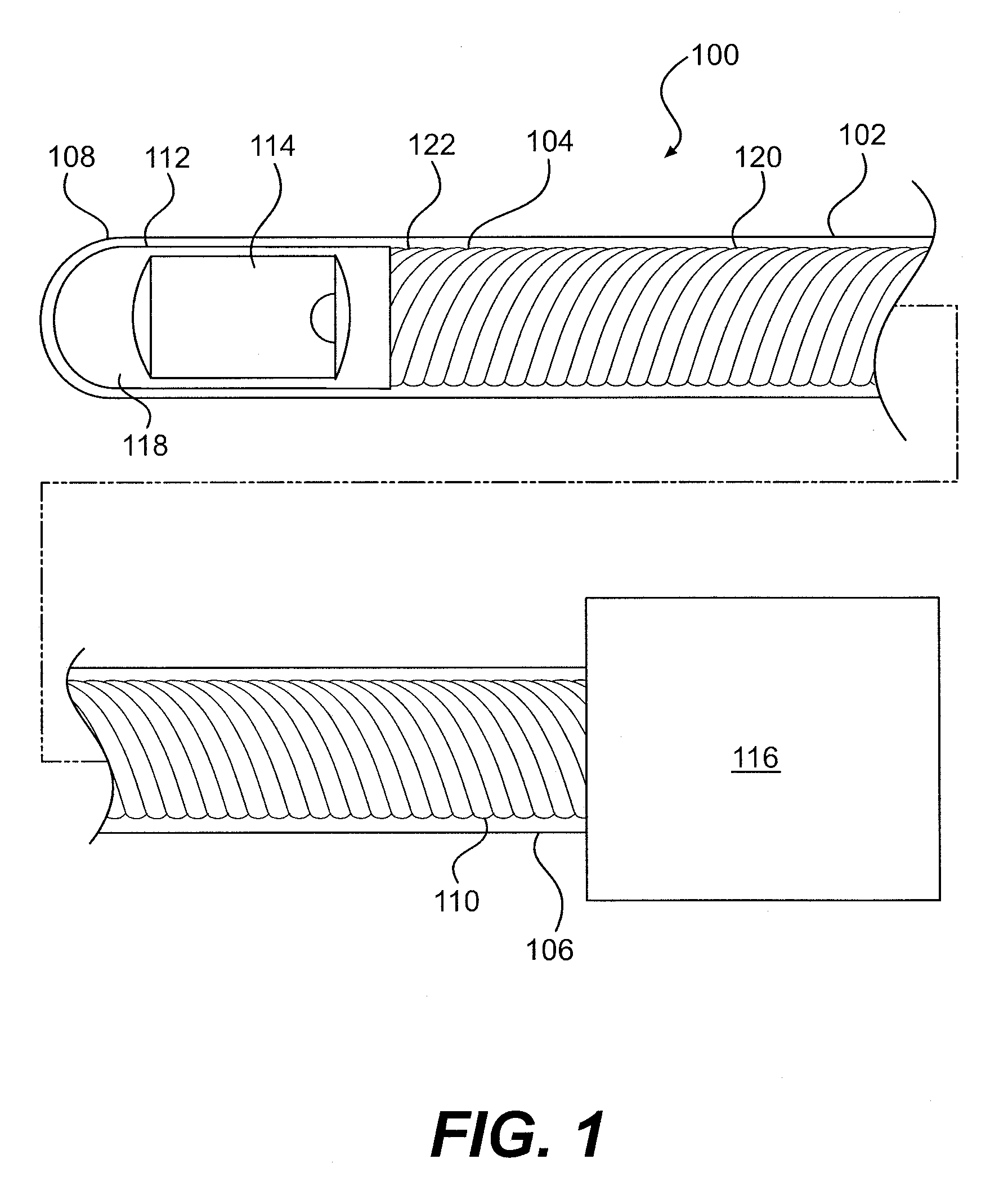
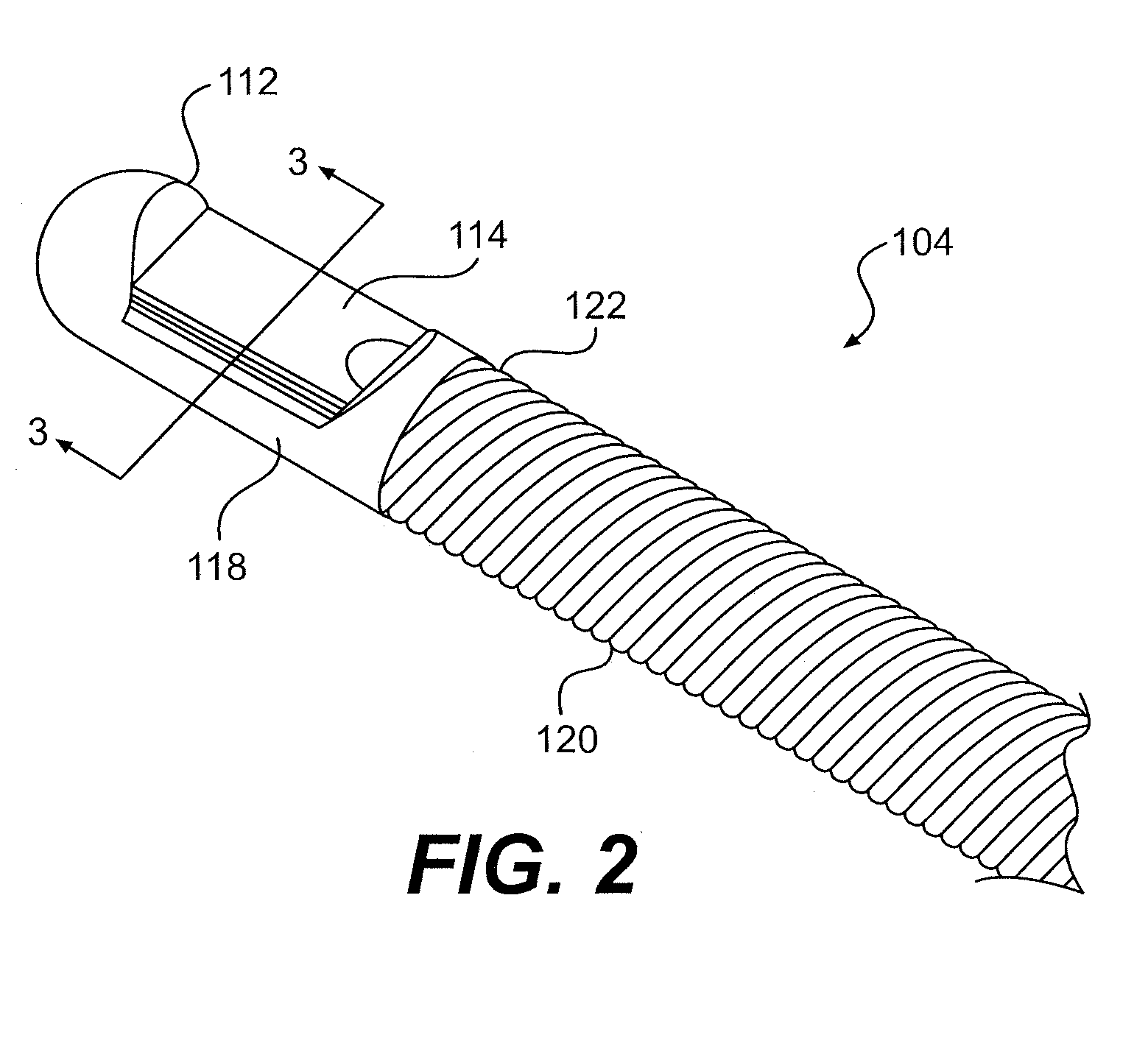
[0018]Turning to the figures, representative illustrations of the rotational intravascular ultrasound (IVUS) probe having a molded transducer housing and a method of molding the same are shown therein. Referring specifically to FIG. 1, a rotational intravascular ultrasound (IVUS) probe 100 for insertion into a patient for diagnostic imaging is shown. The probe 100 comprises a catheter body 102 and a transducer shaft 104. The catheter body 102 is flexible and has both a proximal end portion 106 and a distal end portion 108. The catheter body 102 is a sheath surrounding the transducer shaft 104. For explanatory purposes, the catheter body 102 in FIG. 1 is illustrated as visually transparent such that the transducer shaft 104 disposed therein can be seen, although it will be appreciated that the catheter body 102 may or may not be visually transparent. The transducer shaft 104 is flushed with a sterile fluid, such as saline, within the catheter body 102. The fluid serves to eliminate t...


PUM

PropertyMeasurementUnit
Sizeaaaaaaaaaa
Flexibilityaaaaaaaaaa
Shapeaaaaaaaaaa

Abstract

A rotational intravascular ultrasound probe for insertion into a vasculature and a method of manufacturing the same. The rotational intravascular ultrasound probe comprises an elongate catheter having a flexible body and an elongate transducer shaft disposed within the flexible body. The transducer shaft comprises a proximal end portion, a distal end portion, a drive shaft extending from the proximal end portion to the distal end portion, an ultrasonic transducer disposed near the distal end portion for obtaining a circumferential image through rotation, and a transducer housing molded to the drive shaft and the ultrasonic transducer.

Description

BACKGROUND[0001]Intravascular Ultrasound (IVUS) has become an important interventional diagnostic procedure for imaging atherosclerosis and other vessel diseases and defects. In the procedure, an IVUS catheter is threaded over a guidewire into a blood vessel of interest, and images are acquired of the atherosclerotic plaque and surrounding area using ultrasonic echoes. This information is much more descriptive than the traditional standard of angiography, which only shows an image of the blood flowing through the vessel lumen. Some of the key applications of IVUS include: determining a correct diameter and length of a stent to choose for dilating an arterial stenosis, verifying that a post-stenting diameter and luminal cross-section area are adequate, verifying that a stent is well apposed against a vessel wall to minimize thrombosis and optimize drug delivery (in the case of a drug eluting stent) and identifying an exact location of side-branch vessels. In addition, new techniques ...

Claims


Application Information

Patent Timeline
IPC IPC(8): A61B8/12H04R31/00
CPCA61B5/0066A61B5/0084A61B5/0095A61B8/12A61B8/4461Y10T29/49005A61B8/445A61B8/4444B29C45/0053B29C45/14549A61B8/0891A61B8/08A61B8/0833A61B8/085A61B8/44A61B8/4455A61B8/4483A61B8/4494G01S7/52092G01S15/8952
Inventor DAVIES, STEPHEN CHARLESHOSSACK, NORMANSMITH, PETER HOWARD
Owner VOLCANO CORP
Why Eureka
Try Eureka