Device for vibration compensation of the weight signal of a weighing sensor

a technology of vibration compensation and weighing sensor, which is applied in the direction of weighing auxiliary devices, weighing apparatus details, instruments, etc., can solve the problems of insufficient no longer being in an acceptable range, and not being able to achieve optimal adjustment of image filter, etc., to achieve high measurement accuracy

Active Publication Date: 2010-06-24
WIPOTEC WIEGE UND POSITIONIERSYSTEME GMBH
View PDF7 Cites 12 Cited by
  • Summary
  • Abstract
  • Description
  • Claims
  • Application Information

AI Technical Summary

Benefits of technology

[0008]The invention provides a device for vibration compensation of the weight signal of a weighing sensor that ensures high measurement accuracy. Further, the invention allows such accuracy when using acceleration sensors that are not structurally identical to the actual load cell or the weighing sensor, and even when the load force acting on the weighing sensor covers a large range. In addition, the invention realizes a weighing device with such a device for vibration compensation.
[0010]In this way, by means of each compensation signal branch, the effect of an interference acceleration force can be taken into account, each with a defined degree of freedom, by generating a corresponding noise quantity signal. The possibly multiple noise quantity signals are then subtracted from the still distorted measurement signal. In each of the individual compensation signal branches, through the corresponding tracking of the frequency response of the weighing signal branch with reference to the respective noise quantity, the noise quantity dependent on the total load acting on the weighing sensor can be correctly determined and taken into account.
[0019]According to one embodiment of the invention, the digital filter and thus also each of the one or more first or second digital filters can be divided into several second-order filters or can each consist of a second-order filter. In this way, the design of the filter is simplified. For those second-order sub-filters that are formed as adaptive sub-filters, a simpler functional dependence of the filter parameters on the control variable is produced.

Problems solved by technology

There is also the possibility that not only relatively high-frequency, but also low-frequency interference acceleration forces act on the weighing sensor.
Corresponding low-frequency interference acceleration forces can rarely be eliminated with a typical low-pass filter, because, in this case, the cutoff frequency of the low-pass filter must be selected so low that the settling time no longer lies in an acceptable range.
One problem in this state of the art is that the dynamic behavior of the weighing sensor depends on the applied mass, that is, on the load force, and therefore, in the case of changing mass or varying load force, the image filter is no longer optimally adjusted.
This, however, runs counter to the demand for smaller structural size and high measurement-related sensitivity, where this feature often plays a significant role.

Method used


Image

  • Device for vibration compensation of the weight signal of a weighing sensor
  • Device for vibration compensation of the weight signal of a weighing sensor
  • Device for vibration compensation of the weight signal of a weighing sensor

Examples


Embodiment Construction

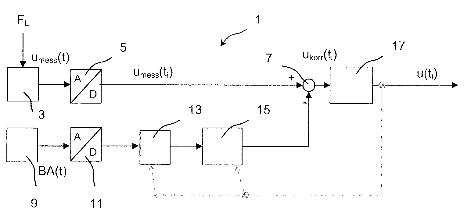
[0027]FIG. 1 shows in a schematic block diagram of a weighing device 1, showing only the components relevant for the understanding of the present invention. The weighing device 1 comprises a weighing sensor 3 that is loaded with a load force FL from a mass mL to be weighed on a load transducer of the weighing sensor 3. The weighing sensor can function according to the principle of the electromagnetic force compensation or according to any other possible physical principle for detecting the weight of a mass mL to be weighed. Here, for the present invention, it is insignificant whether the weighing sensor 3 is formed as an individual load cell and, for example, integrated with an analog / digital converter unit 5 or whether the weighing sensor 3 exists as a separate, stand-alone unit.

[0028]The initially still analog measurement signal or weighing signal umess(t) of the weighing sensor 3 is fed to the converter input of the analog / digital converter unit 5 that generates, at its output, a...


PUM


Abstract

Device for vibration compensation of weighing sensor weight signals, with a weighing signal branch having an analog / digital converter unit to which a weighing sensor analog weighing signal is fed, and that generates a digital weighing signal that contains discrete sample values of the sampled analog weighing signal of the weighing sensor. At least one compensation signal branch has an analog / digital converter unit to which an acceleration sensor analog noise quantity is fed for detecting a specified acceleration noise quantity, and that generates a digital noise quantity signal containing discrete sample values of the acceleration sensor analog noise quantity signal. The digital noise quantity signal is fed to an adaptive digital filter unit. An addition unit sums the signal values of the digital weighing signal and the signal values (carrying a negative sign) for the digital noise quantity signals fed to it.

Description

FIELD OF THE INVENTION[0001]The invention relates to a device for vibration compensation of the weight signal from a weighing sensor as well as a weighing device with such a device for vibration compensation.BACKGROUND[0002]In order to keep the number of weighing processes per time interval as high as possible, in conventional weighing devices it is known to send the measurement signal through only a low-pass filter with a relatively high cutoff frequency. This produces the desired low settling time for the filtered measurement signal. If, in addition to the load to be detected, interference acceleration forces also act on the weighing sensor, for example, in the form of relatively high-frequency vibrations, then such interference on the measurement signal can be eliminated at the output of the weighing device by means of the low-pass filter.[0003]There is also the possibility that not only relatively high-frequency, but also low-frequency interference acceleration forces act on the...

Claims


Application Information

Patent Timeline
Patent Type & Authority Applications(United States)
IPC IPC(8): G01G19/00G01G23/01
CPCG01G23/10
Inventor GOTTFRIEDSEN, JANSCHULZKI, ALEXANDER
Owner WIPOTEC WIEGE UND POSITIONIERSYSTEME GMBH
Why Eureka
Try Eureka