Rotationally Balanced Camshaft Assembly

a camshaft and rotational balance technology, applied in the direction of valve details, valve arrangements, valve drives, etc., can solve the problems of unfavorable rotational balance, camshaft assembly, etc., and achieve the effect of zero balan

Inactive Publication Date: 2010-07-01
DELPHI TECH INC
View PDF6 Cites 8 Cited by
  • Summary
  • Abstract
  • Description
  • Claims
  • Application Information

AI Technical Summary

Benefits of technology

[0008]Briefly described, a method in accordance with the present invention intentionally imbalances one or more mass elements of a camshaft assembly to provide overall rotational balance to the assembly, also referred to herein as “zero balance”. Such intentional imbalance may be imparted to any element of a camshaft assembly, including any new element (counterweight) or plurality of elements provided expressly for that purpose. In a currently-preferred embodiment, one or more components of a camshaft phaser assembly are manufactured as rotationally unbalanced, either by intentionally forming an unbalanced component such as a sprocket wheel having added material or by removing non-functional material from an otherwise balanced component. Because the camshaft phaser assembly has a unique and fixed angular relationship to the camshaft, zero balance can be readily and repeatedly achieved for all camshaft assemblies by correct manufacture of parts without requiring separate balancing for each individual camshaft assembly as manufactured.

Problems solved by technology

Such intentional imbalance may be imparted to any element of a camshaft assembly, including any new element (counterweight) or plurality of elements provided expressly for that purpose.

Method used


Image

  • Rotationally Balanced Camshaft Assembly
  • Rotationally Balanced Camshaft Assembly
  • Rotationally Balanced Camshaft Assembly

Examples


Embodiment Construction

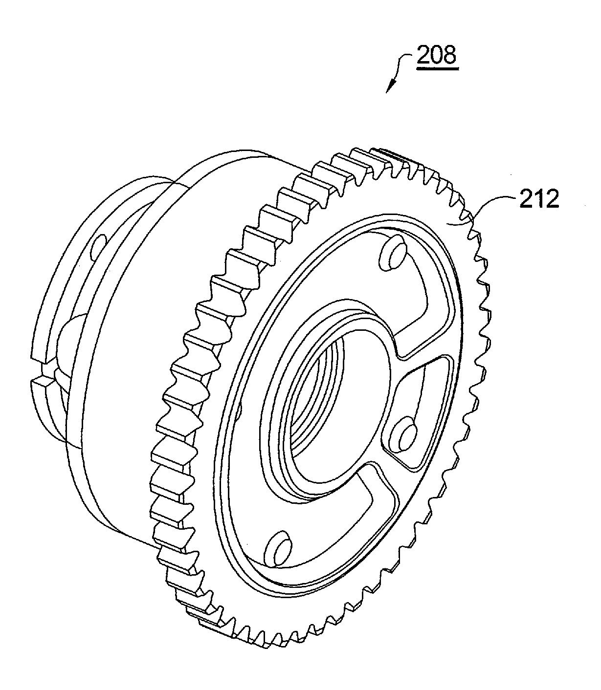
[0018]The object of the present invention is to rotationally balance (zero-balance) a camshaft assembly using components within the camshaft assembly, preferably by intentional imbalancing of an incorporated camshaft phaser assembly. Re-balance can be accomplished using any of the non-functional areas of such components and / or by adding material as counterweights. Both adding mass features and removing mass can affect imbalance and a combination of the two can be used to achieve the end result. A secondary objective of the present invention is to accomplish the abovementioned without an increase in part count, complexity, or cost. Because of its relatively large mass and diameter, the camshaft phaser assembly is a preferred site for creation of such component imbalance.

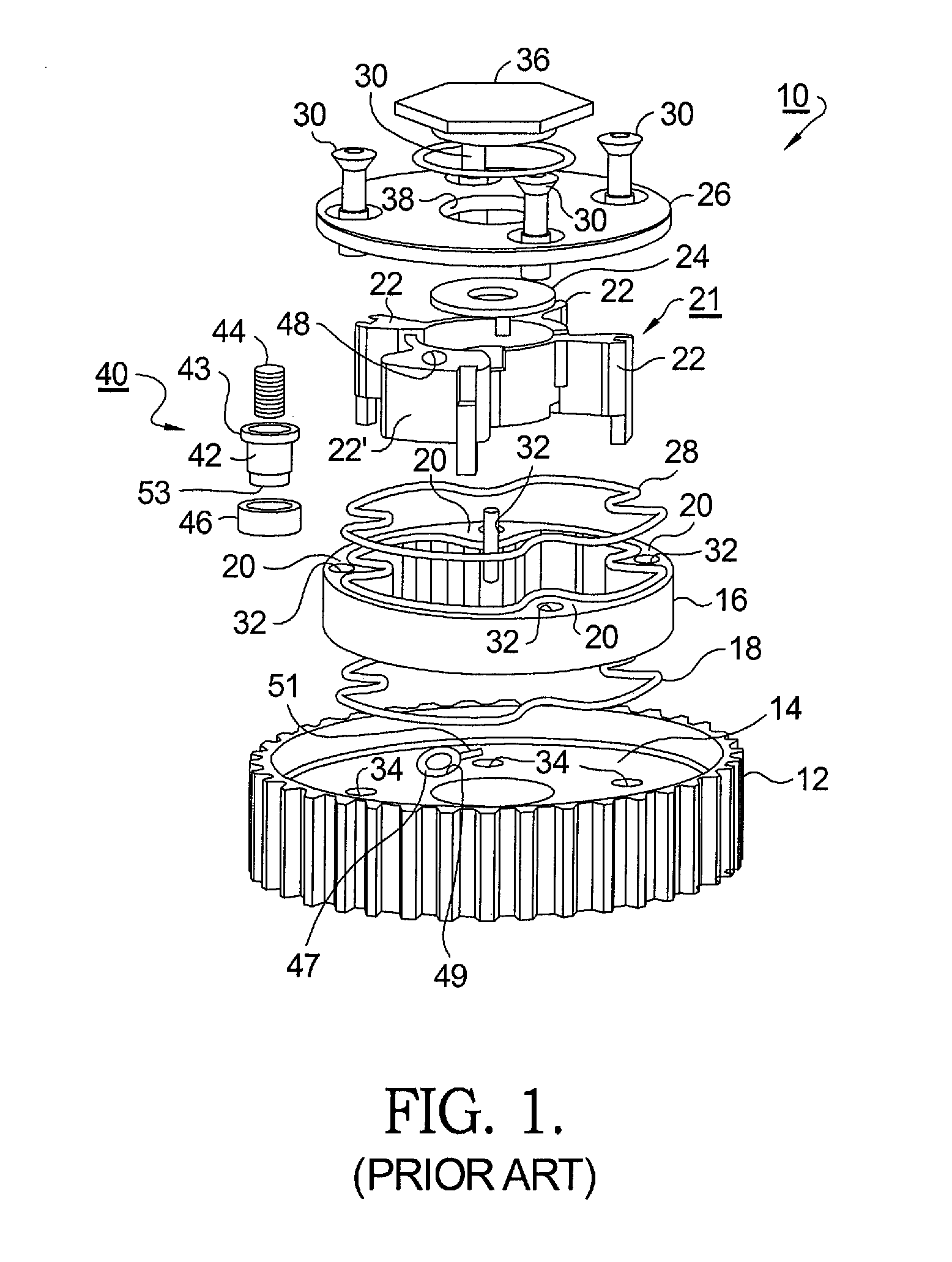
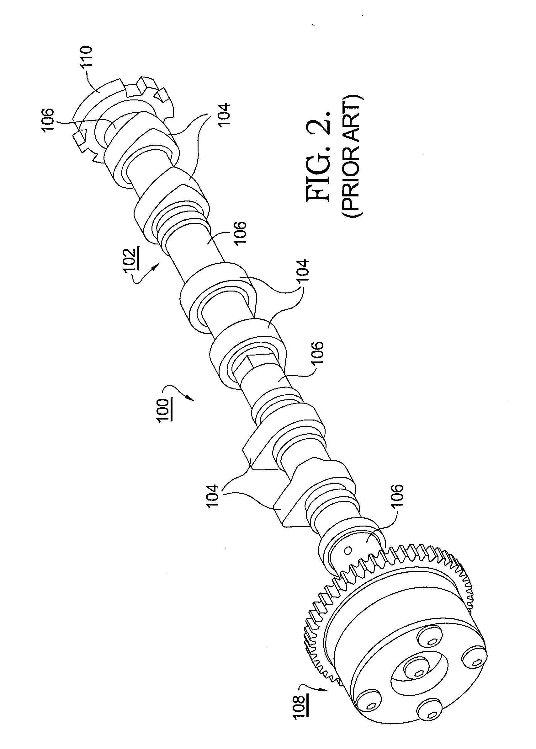
[0019]Referring to FIG. 1, a typical prior art vane-type camshaft phaser assembly 10 includes a pulley or sprocket wheel (pulley / sprocket) 12 for engaging a timing chain or belt (not shown) operated by an engine crank...


PUM


Abstract

A method for intentionally imbalancing one or more mass elements of a camshaft assembly to provide overall rotational balance to the assembly, also referred to herein as “zero balance”. Such intentional imbalance may be imparted to any element of a camshaft assembly. In a currently-preferred embodiment, one or more components of an improved camshaft phaser assembly are manufactured as rotationally unbalanced, either by intentionally forming an unbalanced component such as a sprocket wheel having added material or by removing non-functional material from an otherwise standard component. Because the camshaft phaser assembly has a unique and fixed angular relationship to the camshaft, zero balance can be readily and repeatedly achieved for all camshaft assemblies by correct manufacture of parts without requiring separate balancing for each individual camshaft assembly as manufactured.

Description

RELATIONSHIP TO OTHER APPLICATIONS AND PATENTS[0001]This application claims the benefit of U.S. Provisional Application No. 61 / 203,895, filed Dec. 30, 2008.TECHNICAL FIELD[0002]The present invention relates to rotational balancing of an internal combustion engine; more particularly, to rotational balancing of a camshaft assembly; and most particularly, to a rotationally balanced camshaft assembly manufactured by using an intentionally unbalanced element of the camshaft assembly, and especially a component of a camshaft phaser, to achieve rotational balance of the overall assembly.BACKGROUND OF THE INVENTION[0003]It is well known in the engine arts to achieve overall rotational balance of the crankshaft assembly of an internal combustion engine by strategic removal of material from one or more rotational elements of the crankshaft assembly, such as a flywheel, a balancer, and / or the crank throws. Heretofore, comparable rotational balancing of an engine camshaft has not been disclosed...

Claims


Application Information

Patent Timeline
Patent Type & Authority Applications(United States)
IPC IPC(8): F01L1/04
CPCF01L1/047F01L1/3442F01L2103/00F01L2800/15F01L1/08F01L2303/00F01L2303/02
Inventor STRANDBURG, III, ALAN G.NIEVES, TIMOTHY M.
Owner DELPHI TECH INC
Why Eureka
Try Eureka