Electrostatic motor

a technology of electrostatic motor and motor, which is applied in the direction of electrostatic generator/motor, electrostatic motor, electric motor, etc., can solve the problems of prone to dielectric breakdown, creeping discharge, spark discharge, etc., and achieves sufficient driving force, prevent dielectric breakdown, and improve efficiency

Active Publication Date: 2010-07-01
SHINSEI CO LTD
View PDF7 Cites 8 Cited by
  • Summary
  • Abstract
  • Description
  • Claims
  • Application Information

AI Technical Summary

Benefits of technology

[0006]Another object of the present invention is to provide an electrostatic motor designed so as to prevent dielectric breakdown, creeping discharge, spark discharge, and the like to operate in a strong electric field, and also to be lightweight.
[0017]The present invention adopts the foregoing configuration in which the first and second electrodes attached to the electrode supports of the stator and the rotor are located within the vacuum. Accordingly, unlike a conventional electrostatic motor in which groups of electrodes are supported by an insulator or insulators, the present invention prevents dielectric breakdown even if there is a strong electric field between the electrodes. This results in output as high as or higher than that obtained by an electromagnetic motor. Accordingly, an electrostatic motor that generates a strong electric field in the vacuum such that it can rotationally drive with sufficient driving force can be provided. An electrostatic motor that can drive in a high, clean vacuum is applicable, for example, in semiconductor manufacturing apparatuses. In addition, the electrostatic motor is free from windage loss, thus offering improved efficiency. Moreover, an electrostatic motor that drives in a strong electric field generated between the electrodes allows practical applications including small or large motors, and achieves high output and weight reduction.
[0018]In the present invention, the electrode supports are insulatively supported and grooves are formed in the insulator, allowing sufficient distance for creepage. Accordingly, an electrostatic motor effectively prevents dielectric breakdown, creeping discharge, spark discharge, and other concerns, and generates a strong electric field.
[0019]Additionally, in the electrostatic motor according to the present invention, a stainless steel etc. or an inorganic insulator that produce less residual gas, such as porcelain or glass, are used as components. Therefore, the electrostatic motor can be used in the clean vacuum. Further, using a nonmagnetic material as a metallic components results in a nonmagnetic motor, which can be used in a strong magnetic field.
[0020]Furthermore, the electrostatic motor according to the present invention uses no heavy magnetic materials as metallic components and is therefore lighter in weight than conventional ones.

Problems solved by technology

However, conventional electric motors using electromagnetic force generated by a coil and magnet produce gas in a vacuum, breaking up the vacuum.
In addition, since conventional electric motors use magnetic materials, they cannot be operated in strong magnetic fields.
However, this method is prone to dielectric breakdown, creeping discharge, spark discharge, and other concerns.
Accordingly, a strong electric field cannot be generated, and sufficient driving force cannot be produced.
Therefore, practical electrostatic motors have not yet been realized.

Method used


Image

  • Electrostatic motor
  • Electrostatic motor
  • Electrostatic motor

Examples


first embodiment

[0045]Additionally, in the first embodiment, stainless steel or the like that produce less residual gas may be used as metallic components that are placed in the vacuum container 11 (e.g., the first and second electrodes 34A, 34B, electrode supports 31, 32, first and second electrodes 44A, 44B, and electrode supports 41, 42). Also, an inorganic insulator such as porcelain or glass, which produces less residual gas, may be used as an insulating components. The usability of the electrostatic motor in the clean vacuum can thereby be ensured. It is also effective to deposit a gas absorbing material (i.e., gettering substance), such as titanium, vanadium, tantalum, or zirconium, on components used in the vacuum container 11.

[0046]In the first embodiment, using a nonmagnetic material as the metallic components used in the vacuum container 11 enables a nonmagnetic motor that can be used in a strong magnetic field. Additionally, no heavy magnetic material is used as the metallic components,...

second embodiment

[0052]Next, an electrostatic motor according to the present invention will be described.

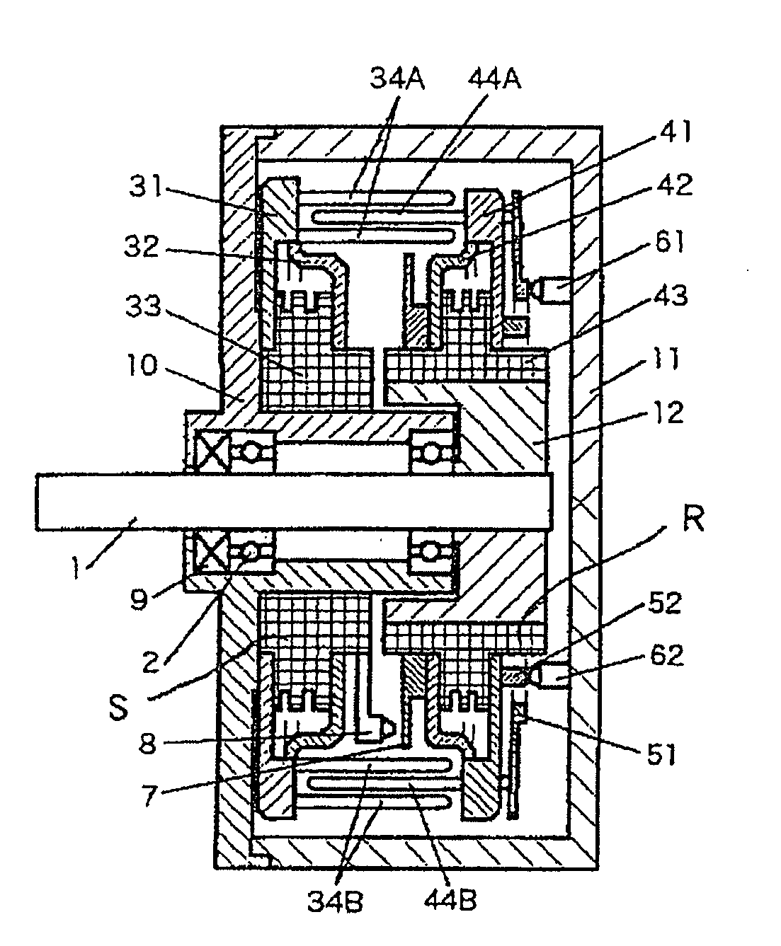
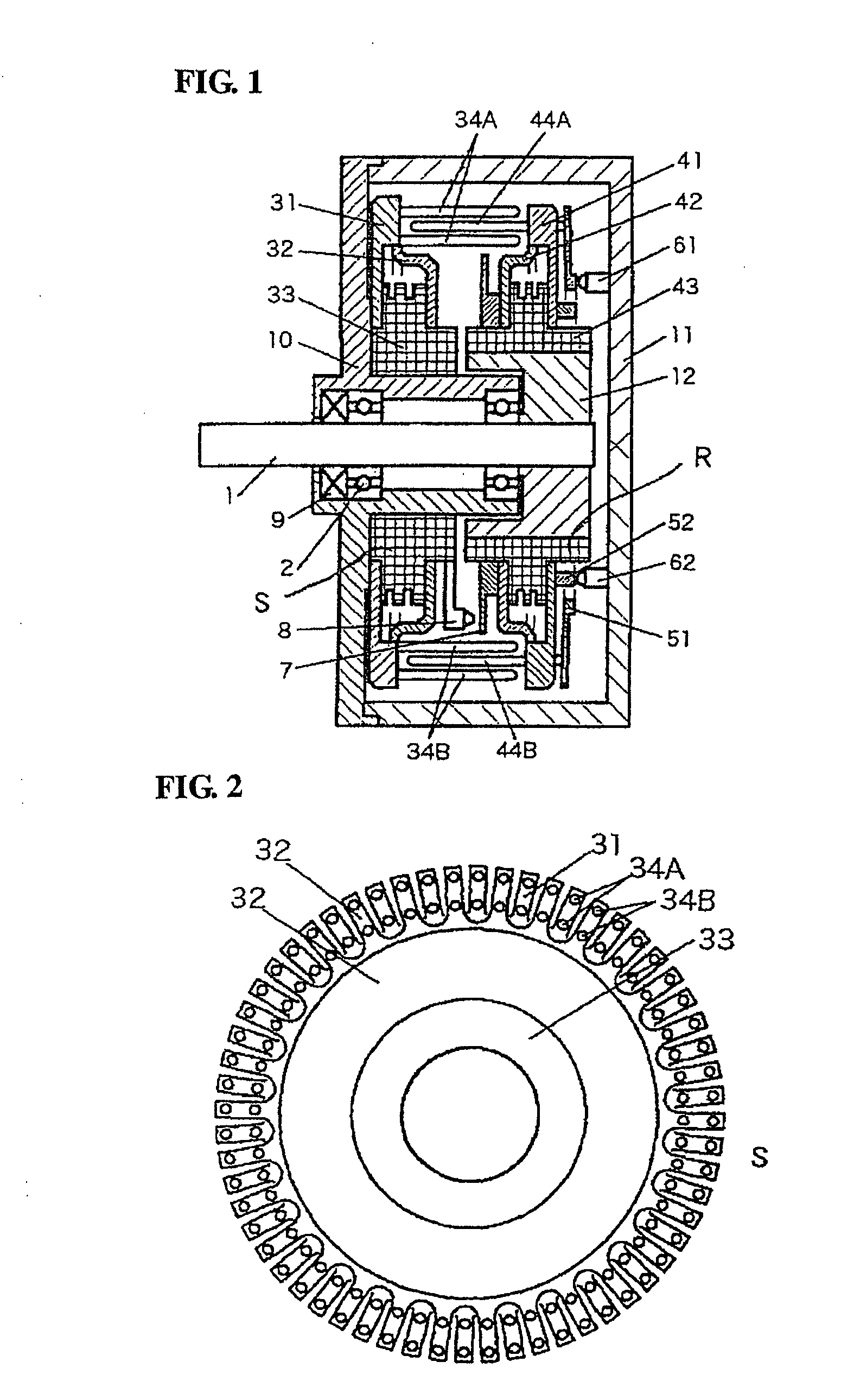
[0053]FIG. 8 shows a vertical section of an electrostatic motor according to the second embodiment. In FIG. 8, elements identical to those in the illustrations of the first embodiment are labeled with the same symbols and duplicate explanation of these elements is avoided.

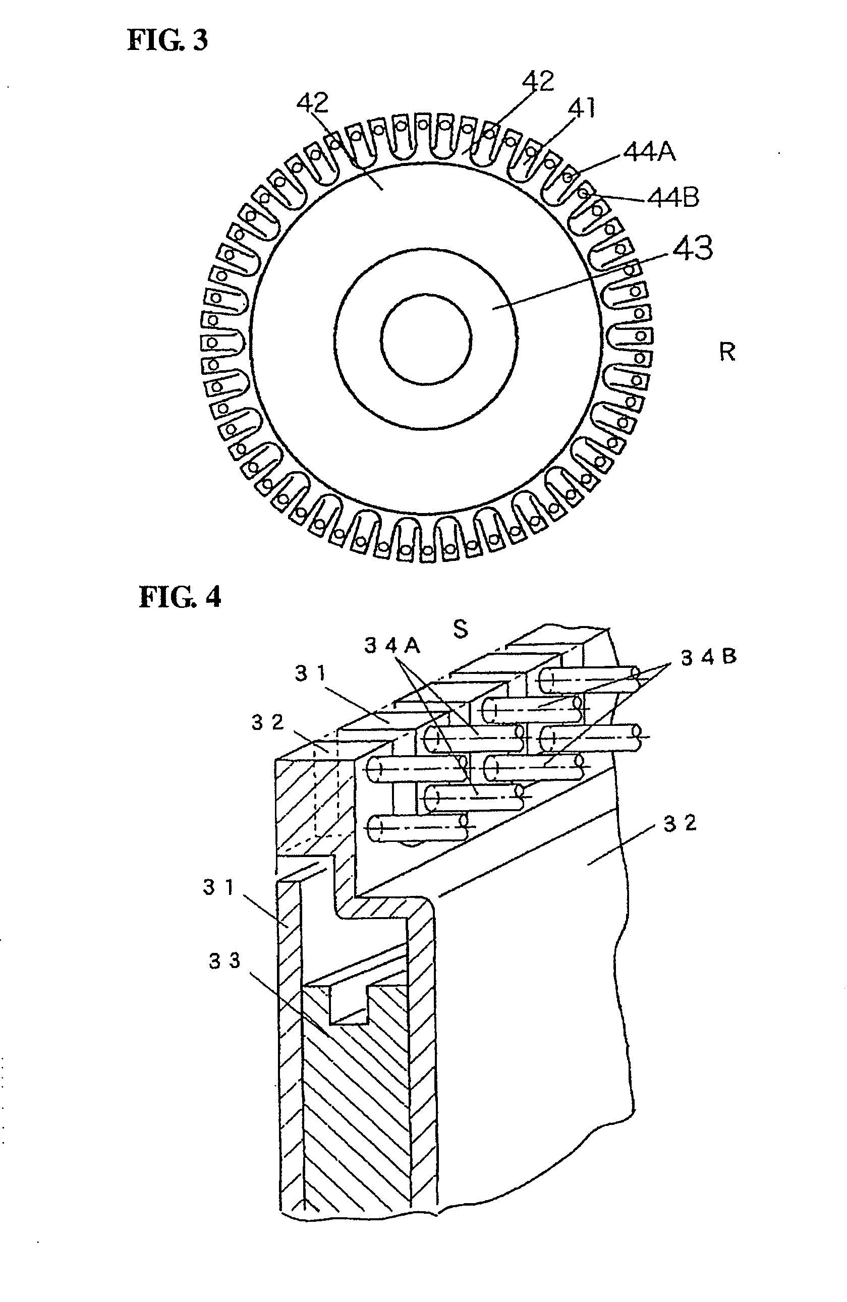
[0054]In the second embodiment, three rows of first electrodes 34A and three rows of second electrodes 34B are disposed along the circumferences of electrode supports 31, 32 respectively, on the stator S side. Similarly, two rows of first electrodes 44A and two rows of second electrodes 44B are disposed along the circumferences of electrode supports 41, 42 respectively. In the second embodiment, an electrostatic motor with a high output is produced by increasing the number of electrodes.

third embodiment

[0055]Next, an electrostatic motor according to the present invention will be described.

[0056]FIG. 9 shows a vertical section of the electrostatic motor according to the third embodiment. In FIG. 9, elements identical to those in the illustrations of the first embodiment are labeled with the same symbols and duplicate explanation of these elements is avoided. The encoder, the slip rings, and the brushes are not shown.

[0057]In the first and second embodiments, limitations resulting from a cantilever structure impede any unnecessary increase in electrode length. In the third embodiment, first electrodes 44A are extended from both sides of each of electrode supports 41 on the rotor R side, and second electrodes 44B are also extended from both sides of each of electrode supports 42 on the rotor R side. This allows an output that is twice as high as that of an electrostatic motor with cantilever structured electrodes in the first embodiment. In addition, the first and second electrodes 3...


PUM


Abstract

Provided is an electrostatic motor, in which a disc-shaped stator (S) and a disc-shaped rotor (R) are opposed to each other in a vacuum container (11). In the stator (S), first electrodes (34A) and second electrodes (34B), which are attached to electrode supports (31, 32), respectively, and which are electrically insulated from each other by an insulator (33), are arranged alternately in the circumferential direction. In the rotor (R), first electrodes (44A) and second electrodes (44B), which are attached to electrode supports (41, 42), respectively, and which are electrically insulated from each other by an insulator (43), are arranged alternately in the circumferential direction. The first electrodes (34A) and the second electrodes (34B) on the side of the stator (S) are arranged at a spacing of two or more rows at a predetermined distance from the center of a rotating shaft (1). The first electrodes (44A) and the second electrodes (44B) on the side of the rotor (R) are arranged at a predetermined distance from the center of the rotating shaft (1) and at an intermediate position between the rows of the first electrodes (34A) and the second electrodes (34B) on the side of the stator (S). As a result, the electrostatic motor can establish a high electric field in the vacuum so that it can rotationally drive with a sufficient driving force.

Description

TECHNICAL FIELD[0001]The present invention relates to an electrostatic motor that rotationally drives using electrostatic force, and in particular to an electrostatic motor that rotationally drives by generating a high electric field in a vacuum.BACKGROUND ART[0002]Most conventional electric motors use electromagnetic force generated by a coil and magnet. Electrostatic motors that rotationally drive using electrostatic force are also known (e.g., Japanese Patent Application Laid-Open No. 8-88984, and Study of Servo System using Electrostatic Motors written by Akio Yamamoto et al., www.intellect.pe.u-tokyo.ac.jp / japanese / dissertation_j / yamamoto.html)[0003]However, conventional electric motors using electromagnetic force generated by a coil and magnet produce gas in a vacuum, breaking up the vacuum. In addition, since conventional electric motors use magnetic materials, they cannot be operated in strong magnetic fields.[0004]Conventional electrostatic motors, as described above, also ...

Claims


Application Information

Patent Timeline
Patent Type & Authority Applications(United States)
IPC IPC(8): H02N11/00
CPCH02N1/004
Inventor SASHIDA, TOSHIIKU
Owner SHINSEI CO LTD
Why Eureka
Try Eureka