
Method for manufacturing inductive electric component, and inductive electric component

a technology of inductive electric components and inductive electric components, which is applied in the direction of transformer/inductance cooling, magnets, magnetic bodies, etc., can solve the problems that the known coiling can involve substantial manual work and manufacturing costs

Inactive Publication Date: 2010-07-01
ABB OY
View PDF4 Cites 10 Cited by
  • Summary
  • Abstract
  • Description
  • Claims
  • Application Information

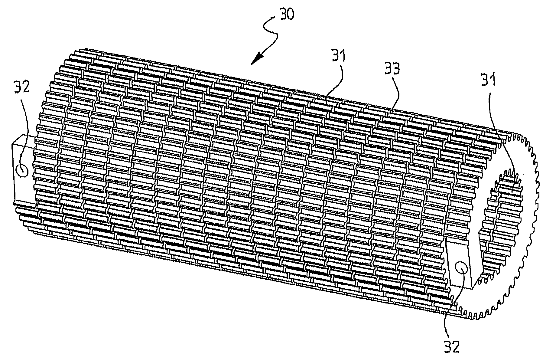
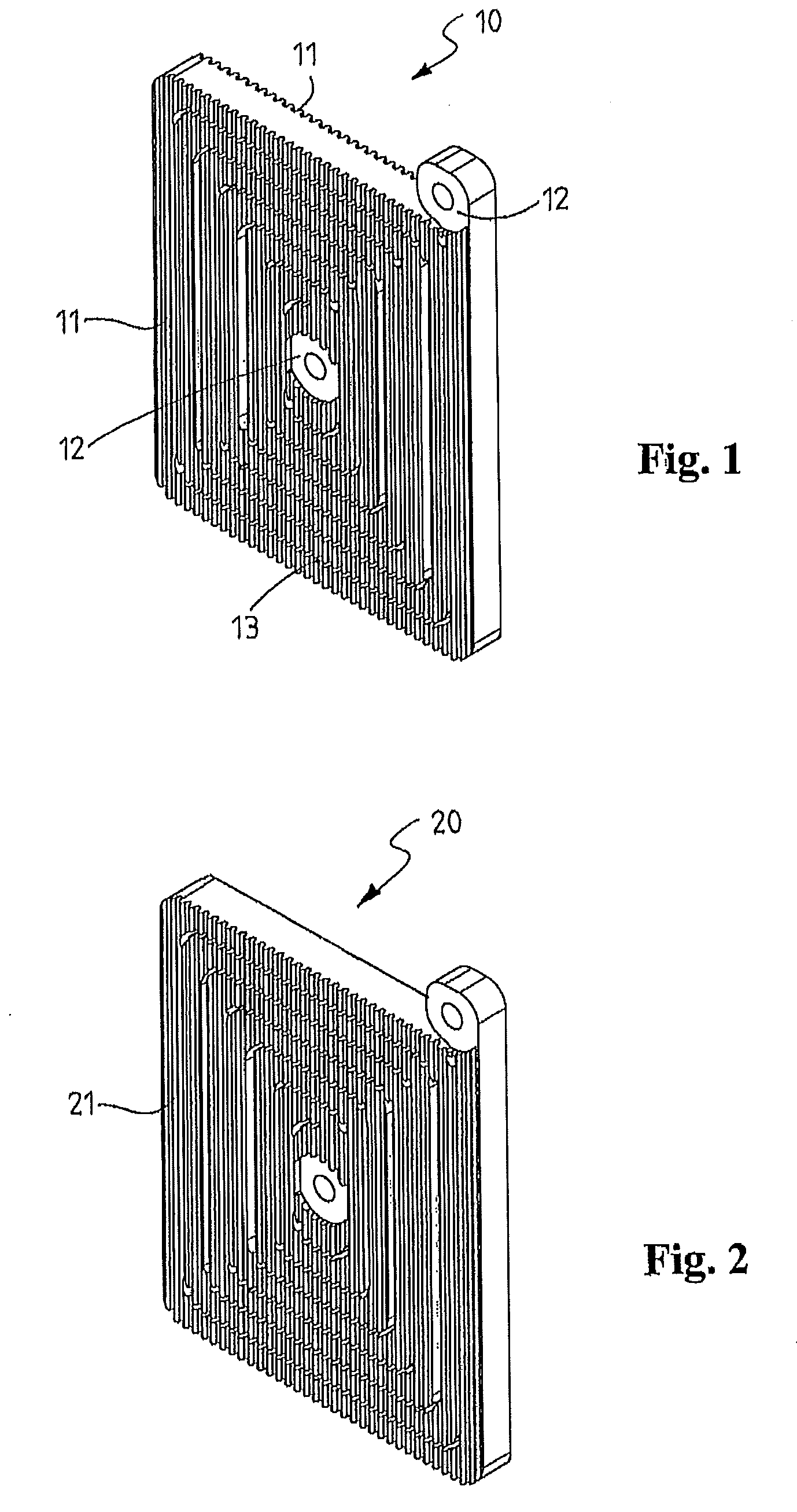
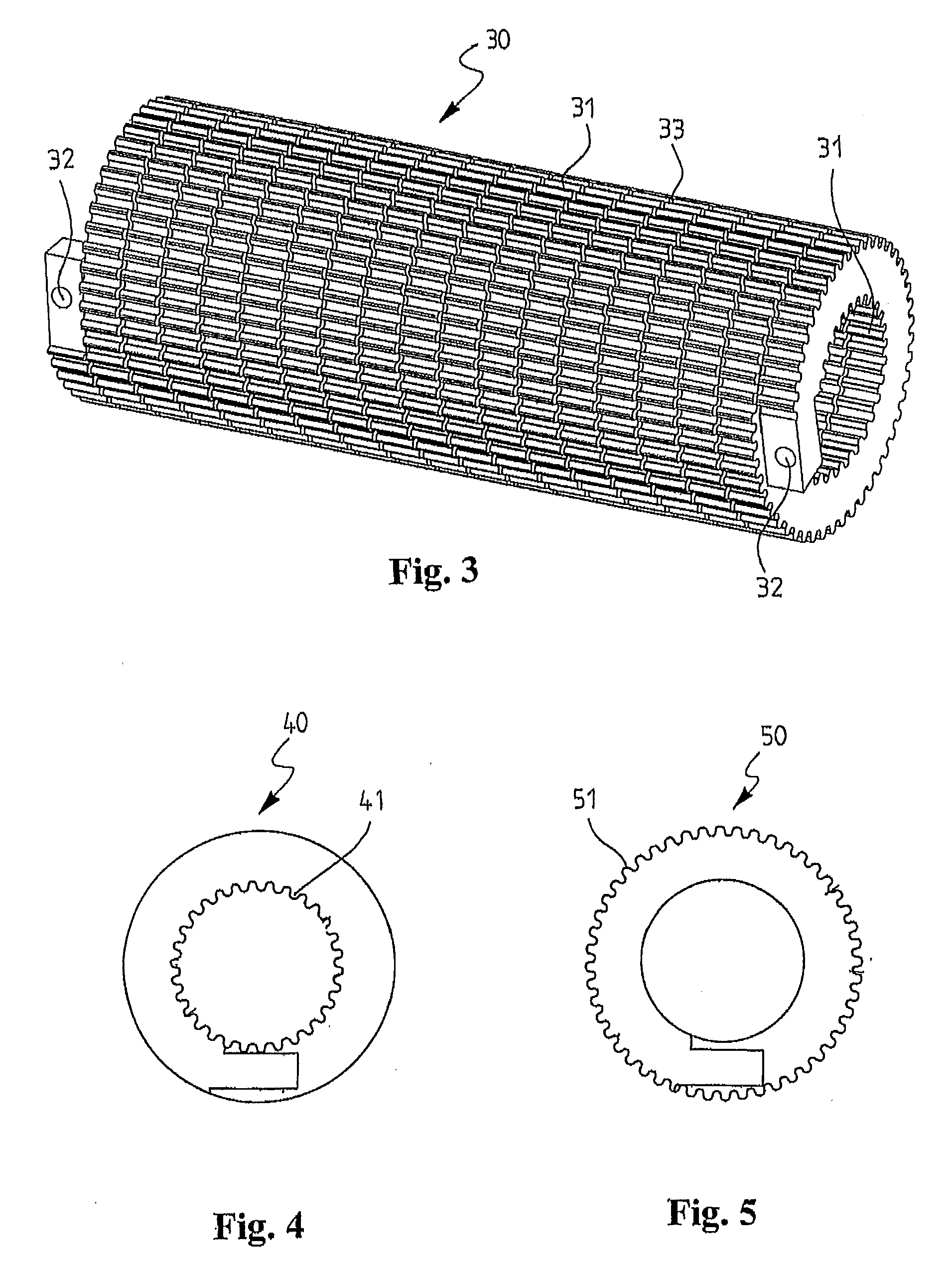
AI Technical Summary

Benefits of technology

[0012]Exemplary methods disclosed herein can provide an efficient air-cooling for the element during its manufacture, and water-cutting can provide a dimensionally accurate product in a modern manner involving a minimum amount of manual work. The method can be flexible and easily applicable to different element shapes. The product can be applied to different currents, and it is possible to manufacture even very small coils.
[0013]The width of the water-cutting groove is, for example, 1 to 2 mm, or lesser or greater. The narrow cutting groove of an element cut from plate material can, for example, be filled with varnish or resin that binds the piece back into a plate-like element. The cut element can also be supported mechanically.
[0015]Where an exemplary water-cutting approach is used in the method, a wide range of materials can be used, and the method can be used to cut thicker materials than with a laser, for example. Water-cutting does not generate heat in the material being cut, which means that the material does not warp during cuting. In water-cutting, the material being cut is penetrated by concentrating a high energy density to it with a thin water jet at approximately 1000 m / s, more or less. This water jet can be provided with a high-pressure pump that generates a high pressure. Water-cutting can be a very efficient, but also a very gentle method. No material burning or melting, gas or slag formation, cracking, breaking, or chemical changes occur in the material being processed. The outlet side of the water jet can remain flawless. Water-cutting can also be done using multiple (e.g., two) techniques, either with water only, or by using abrasive sand in addition to water. For example, when using abrasive sand, the water jet sweeps along from the ejectors hard sand crystals, with which all hard and strong materials can be cut.

Problems solved by technology

Known coiling can involve substantial manual work and costs during manufacture.

Method used


Image

  • Method for manufacturing inductive electric component, and inductive electric component
  • Method for manufacturing inductive electric component, and inductive electric component
  • Method for manufacturing inductive electric component, and inductive electric component

Examples


Embodiment Construction

[0010]An exemplary method and electric component are disclosed wherein a winding (e.g., spiral or coiled element) is formed from a piece furnished with cooling ribs, and wherein the element is formed by water-cutting.

[0011]The component can be, for example, an inductor or resistor element water-cut into a “spring” from plate material or a pipe-like profile having a selected thickness. The starting material can be, for example, extruded aluminum profiles, copper rods and pipes, and stainless steels having different wall thicknesses. At least one surface of the plate material can be furnished with cooling ribs, or at least one of inner and outer surfaces of the pipe profile can be furnished with cooling ribs.

[0012]Exemplary methods disclosed herein can provide an efficient air-cooling for the element during its manufacture, and water-cutting can provide a dimensionally accurate product in a modern manner involving a minimum amount of manual work. The method can be flexible and easily ...


PUM

PropertyMeasurementUnit
widthaaaaaaaaaa
inductanceaaaaaaaaaa
thicknessaaaaaaaaaa

Abstract

A method and electric component, such as inductor, coil, resistor, or the like, are disclosed wherein a winding includes at least one spiral or coiled element, the spiral or coiled element being formed from a piece furnished with cooling ribs.

Description

RELATED APPLICATION[0001]This application claims priority under 35 U.S.C. §119 to Finnish Patent Application No. 20086244 filed in Finland on Dec. 29, 2008, the entire content of which is hereby incorporated by reference in its entirety.FIELD[0002]The disclosure relates to a method for manufacturing an inductive electric component, such as inductor, coil, resistor, or the like, having at least one spiral or coiled element. The disclosure also relates to an inductive electric component of this type.BACKGROUND INFORMATION[0003]An inductive electric component may be an inductor, for instance, that is used in an electric device as a filtering component, for instance. The number of conductor turns, external dimensions, and the core material can affect the inductance of the inductor.[0004]Known spiral or coiled elements are made of filamentous material coiled on the core material. Air-core elements are also coiled on a support structure.[0005]Known coiling can involve substantial manual w...

Claims


Application Information

Patent Timeline
Patent Type & Authority Applications(United States)
IPC IPC(8): H01F27/08H01F7/06
CPCH01F5/00H01F27/085H01F27/2847H01F27/2876H01F41/04Y10T29/4902
Inventor SEVAKIVI, PERTTI
Owner ABB OY
Learn More