Liquid crystal display device

a liquid crystal display and display device technology, applied in the field of can solve the problems of reducing power consumption, deteriorating utilization efficiency of backlight illumination, and difficulty in increasing the aperture ratio of conventional active matrix liquid crystal display devices, so as to improve resolution and aperture ratio, improve the effect of moving image and improving the aperture ratio

Inactive Publication Date: 2010-07-01
PANASONIC CORP
View PDF24 Cites 18 Cited by
  • Summary
  • Abstract
  • Description
  • Claims
  • Application Information

AI Technical Summary

Benefits of technology

[0021]In the above liquid crystal display device, a drive/display operation can be performed by switching between only any two of the three red, green and blue lights, so that a response speed required for the liquid crystal can be reduced to ⅔ as compared with the conventional field sequential driving scheme. This makes it possible to achieve an excellent moving image, for example, even in an OCB mode liquid crystal display panel having a response speed which is hardly adequate for the conventiona

Problems solved by technology

However, the conventional active matrix-type liquid crystal display device has difficulty in increasing a pixel aperture ratio, for the following reason.
This causes a deterioration in utilization efficiency of illuminating light of the backlight illuminator to impose a restriction on the reduction in power consumption, because light never passes through the pixels in a quantity greater than that determined by an aperture ratio of a light-transmissive area of the sub-pixels.
However, this scheme has many problems to be solved, and thereby has not reached a stage of full-scale commercialization.
This allegedly makes it possible to reduce the flicker phenomenon in a display screen which is one disadvantage of the field sequential driving scheme.
In terms of response speed, even

Method used


Image

  • Liquid crystal display device
  • Liquid crystal display device
  • Liquid crystal display device

Examples


first embodiment

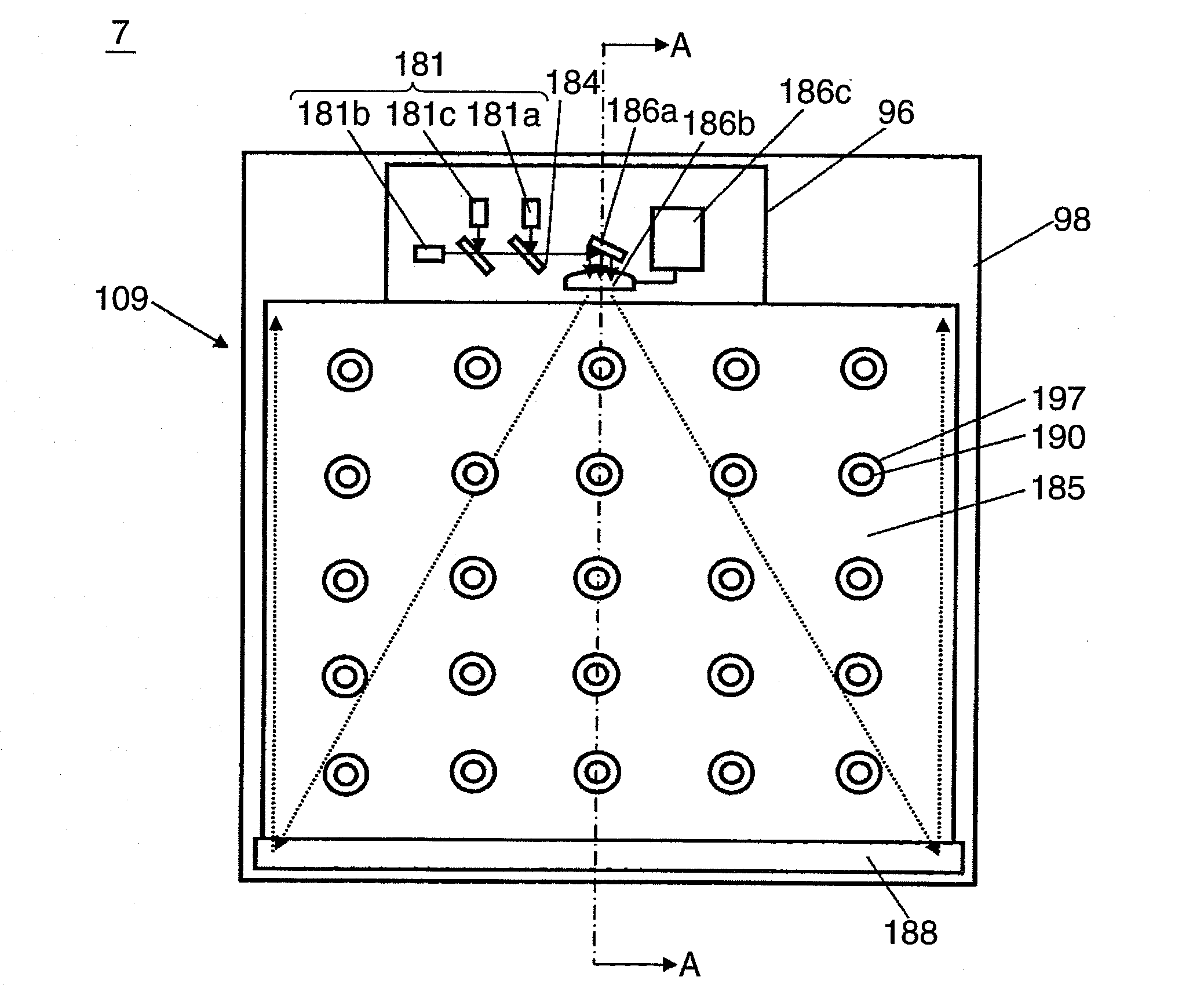
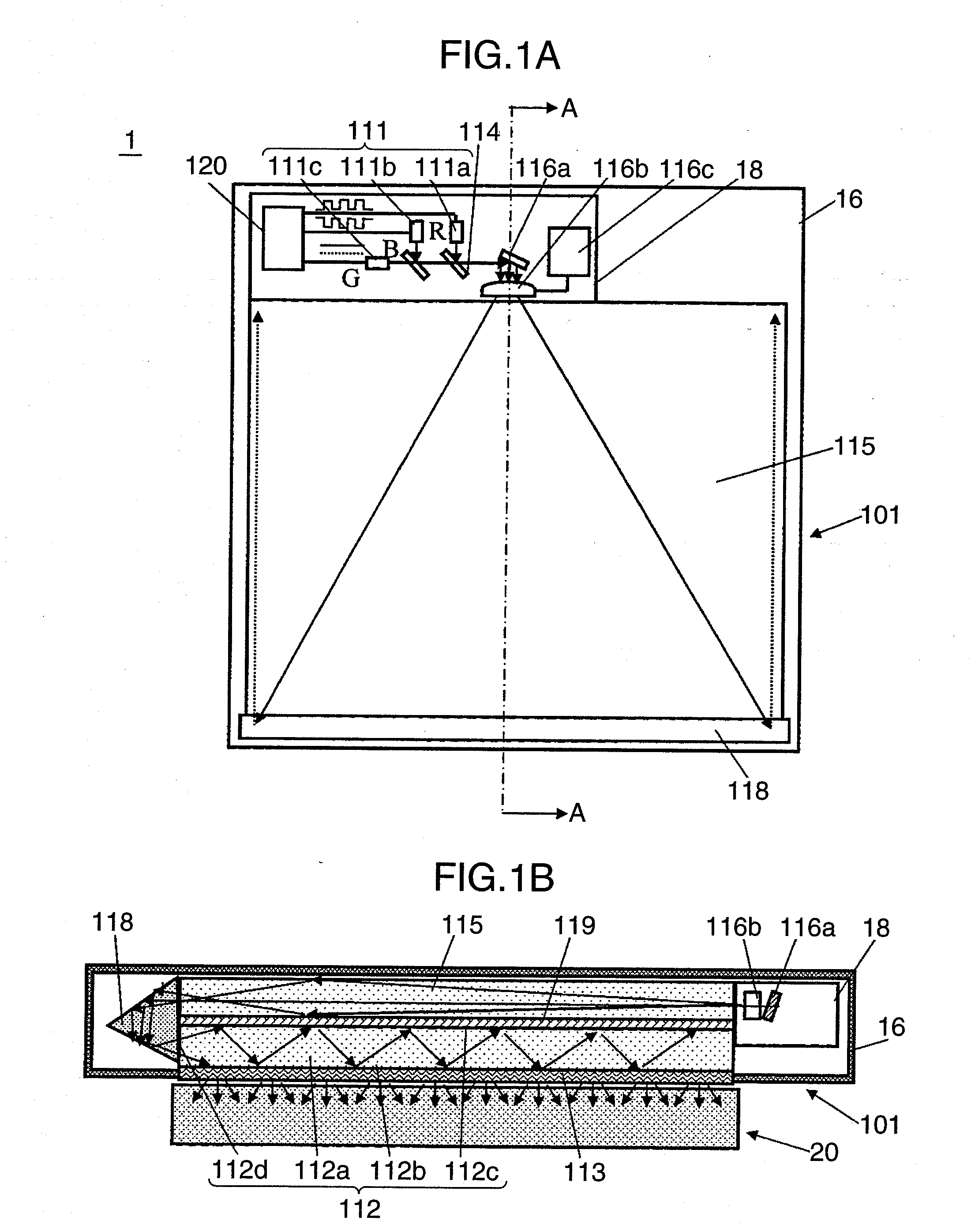
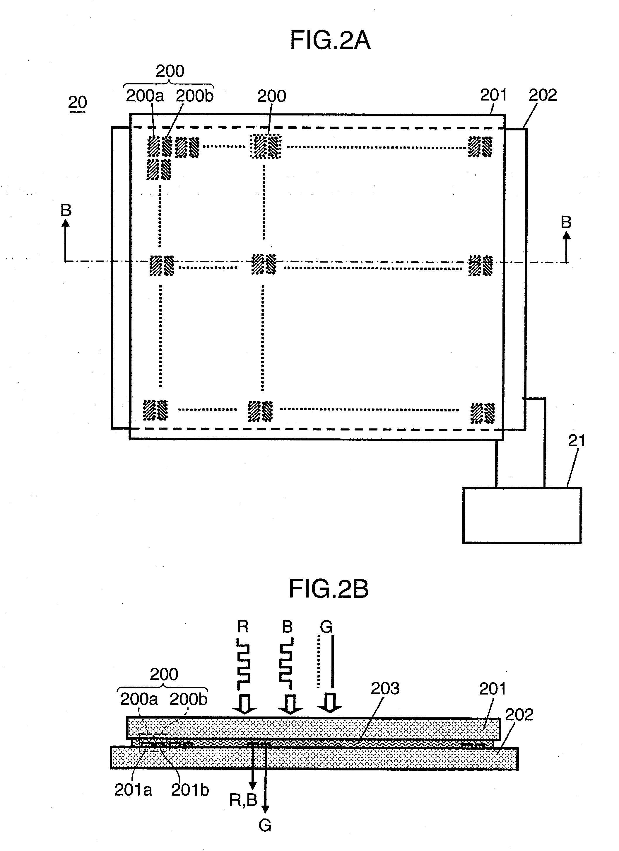
[0042]FIGS. 1A and 1B show a configuration of a liquid crystal display device 1 according to a first embodiment of the present invention, wherein FIG. 1A is a schematic top plan view showing an outline of the configuration of the liquid crystal display device 1, FIG. 1B is a schematic sectional view taken along the line A-A in FIG. 1A. In the illustration of the liquid crystal display device 1, respective surfaces of a housing 16 and a compartment 18 for receiving therein a light source are cut away to show an internal configuration in an easily understandable manner. FIGS. 2A and 2B are conceptual views for explaining a configuration of a liquid crystal display panel 20 for use in the liquid crystal display device 1 according to the first embodiment, wherein FIG. 2A is a schematic top plan view, and FIG. 2B is a conceptual sectional view taken along the line B-B in FIG. 2A. In FIGS. 2A and 2B, the same element as that in FIGS. 1A and 1B is defined by a common code. With reference t...

second embodiment

[0078]FIGS. 4A and 4B show a configuration of a liquid crystal display device 2 according to a second embodiment of the present invention, wherein FIG. 4A is a schematic top plan view showing an outline of the configuration of the liquid crystal display device 2, FIG. 4B is a schematic sectional view taken along the line A-A in FIG. 4A. The same element as that in FIGS. 1A and 1B is defined by a common code, and its description will be omitted on a case-by-case basis. In the illustration of the liquid crystal display device 2, respective surfaces of a housing 26 and a compartment 28 are cut away to show an internal configuration in an easily understandable manner. The liquid crystal display device 2 illustrated in FIGS. 4A and 4B is different from the liquid crystal display device 1 illustrated in FIGS. 1A to 2B, in that a light-emitting diode (LED) is used as a light source for use in a light source section. A configuration of a liquid crystal display panel 2 in the second embodime...

third embodiment

[0093]FIG. 5 is a conceptual sectional view showing a configuration of a liquid crystal display device 4 according to a third embodiment of the present invention. The same element as that in FIGS. 1A to 4B is defined by a common code, and its description will be omitted on a case-by-case basis. The liquid crystal display device 4 illustrated in FIG. 5 is different from the liquid crystal display device 1 according to the first embodiment and the liquid crystal display device 2 according to the second embodiment, in that the liquid crystal display device 4 has a projection-type configuration having a projection-type illuminator as the light source section, wherein parallel lights are emitted from the projection-type illuminator to a surface of a liquid crystal display panel, and transmitted lights are displayed on a screen. A configuration of a liquid crystal display panel 20 illustrated in FIG. 5 is the same as the configuration illustrated in FIGS. 2A and 2B. Thus, the following de...


PUM


Abstract

Disclosed is a liquid crystal display device, which is capable of reducing a required response speed and increasing a pixel aperture ratio, as compared with a field sequential driving scheme. A unit pixel of a liquid crystal display panel is made up of a first sub-pixel adapted to allow only any two of red, green and blue lights to pass therethrough, and a second sub-pixel adapted to allow only a remaining one of the red, green and blue lights to pass therethrough, wherein one frame of image is time-divided into n pieces (wherein n is an integer of two or more), and respective image information about the two lights are applied to the first sub-pixel during every duration of the 1/n frame, while applying image information about the remaining one light to the second sub-pixel during a duration of the one frame of image. Further, the respective two lights are emitted during every duration of the 1/n frame in synchronization with applying the respective image information about the two lights, while continuously emitting the remaining one light during the duration of the one frame of image.

Description

TECHNICAL FIELD[0001]The present invention relates to a liquid crystal display device capable of performing color display with excellent color reproducibility.BACKGROUND ART[0002]Heretofore, among liquid crystal display devices, an active matrix-type liquid crystal display device has been extensively used as a display device for personal computers and liquid crystal televisions. Along with this application, enlargement of a screen has been rapidly progressing. Furthermore, the active matrix-type liquid crystal display device is required to achieve a display with high definition, wide color reproduction range and high image quality, irrespective of size of a display screen. The reason is to more explicitly maintain its superiority in competition with other types of display devices, such as a plasma display panel (PDP). It is also required to achieve a reduction in power consumption.[0003]With a view to reductions in power consumption and cost, efforts to increase a pixel aperture rat...

Claims


Application Information

Patent Timeline
IPC IPC(8): G09G5/10G09G3/36
CPCG09G3/3413G09G3/3607G09G2310/0235G09G2340/06G09G2360/145H04N9/3117
Inventor YAMAMOTO, KAZUHISAMIZUSHIMA, TETSUROITOH, TATSUOKASAZUMI, KENICHIKADOWAKI, SHINICHI
Owner PANASONIC CORP
Why Eureka
Try Eureka