Heater Stack In A Micro-Fluid Ejection Device And Method For Forming Floating Electrical Heater Element In The Heater Stack

a technology of microfluid ejection and heater stack, which is applied in the direction of basic electric elements, electrical apparatus, printing, etc., can solve the problems of large percentage of energy dissipation in materials, dramatic decrease, and limited thermal properties of printheads, so as to reduce the number of fabrication steps and thus the cost of making the device, and achieves easy integration. , the effect of high thermal efficiency

Inactive Publication Date: 2010-07-01
FUNAI ELECTRIC CO LTD
View PDF3 Cites 1 Cited by
  • Summary
  • Abstract
  • Description
  • Claims
  • Application Information

AI Technical Summary

Benefits of technology

[0009]The present invention meets this need by providing an innovation whose differentiating factor, as well as advantage, relative to the Memjet design approach is that a method for forming a floating electrical heater element on a micro-fluid ejection device is devised that is more compatible and easily integrated with the micro-fluid ejection device fabrication processes and techniques used heretofore, such as the currently-used CMOS process. The approach of the method of the present invention provides a substantial reduction in the number of fabrication steps and thus the cost to make the device as compared to the Memjet design approach. The floating electrical heater element formed by the method of the present invention has high thermal efficiency due to reduction of waste heat flow into a mass of the silicon substrate now removed beneath the heater element and increase of bubble nucleation surface area providing more fluid displacement as well as back flow reduction due to bubble nucleation at a backside of the heater element.

Problems solved by technology

However, a large percentage of the energy is dissipated in the materials over and under the heater element.
However, with current inks, flow features and nozzle materials, ejector and circuit designs, and current thin film materials in heater stacks, printheads are thermally limited due to the extreme heat generated on heater elements.
Conversely, reducing the fire frequency for thermal management purposes would require such a dramatic decrease that the print speed would be extremely slow.
While this double-sided heater element does reduce the required energy per fire due to the removal of the thermal mass below the heater element, this approach involves a major departure from the use of conventional inkjet chip fabrication processes and techniques.

Method used


Image

  • Heater Stack In A Micro-Fluid Ejection Device And Method For Forming Floating Electrical Heater Element In The Heater Stack
  • Heater Stack In A Micro-Fluid Ejection Device And Method For Forming Floating Electrical Heater Element In The Heater Stack
  • Heater Stack In A Micro-Fluid Ejection Device And Method For Forming Floating Electrical Heater Element In The Heater Stack

Examples


Embodiment Construction

[0031]The present invention now will be described more fully hereinafter with reference to the accompanying drawings, in which some, but not all embodiments of the invention are shown. Indeed, the invention may be embodied in many different forms and should not be construed as limited to the embodiments set forth herein; rather, these embodiments are provided so that this disclosure will satisfy applicable legal requirements. Like numerals refer to like elements throughout the views.

[0032]Also, the present invention applies to any micro-fluid ejection device, not just to heater stacks for thermal inkjet printheads. While the embodiments of the present invention will be described in terms of a thermal inkjet printhead, one of ordinary skill will recognize that the invention can be applied to any micro-fluid ejection system.

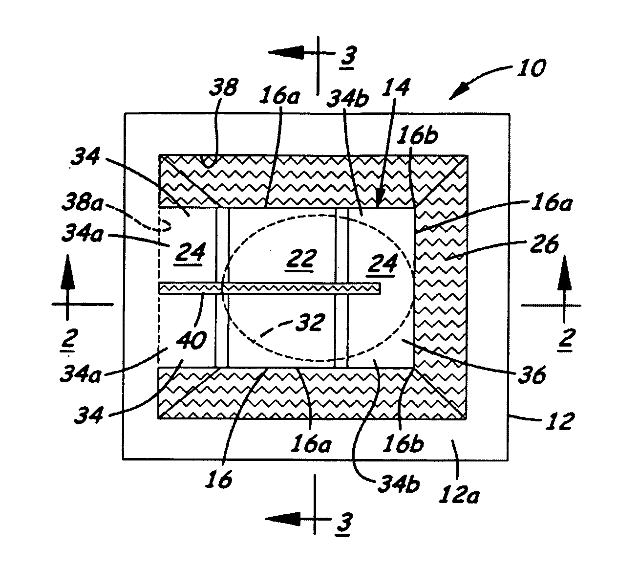
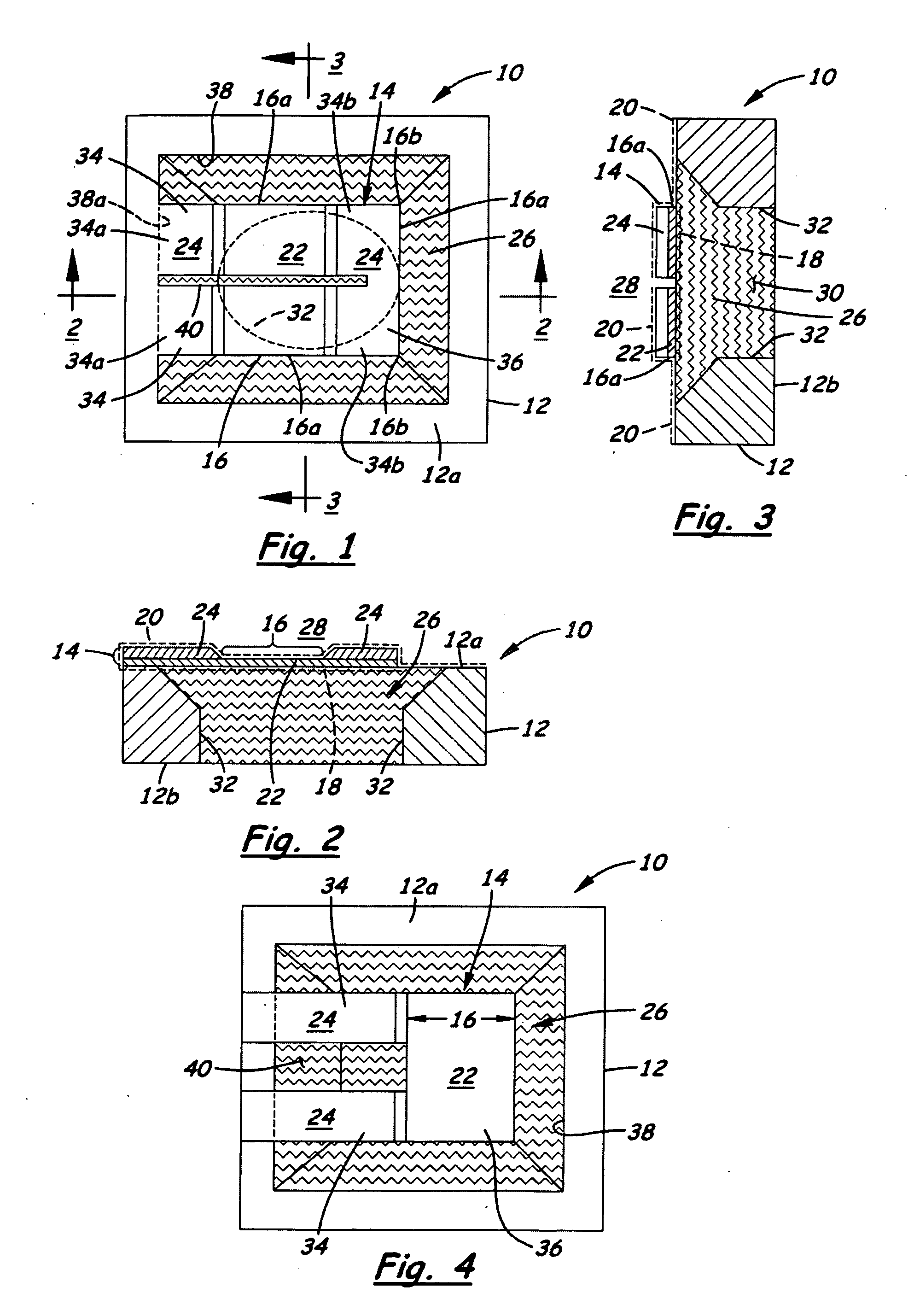
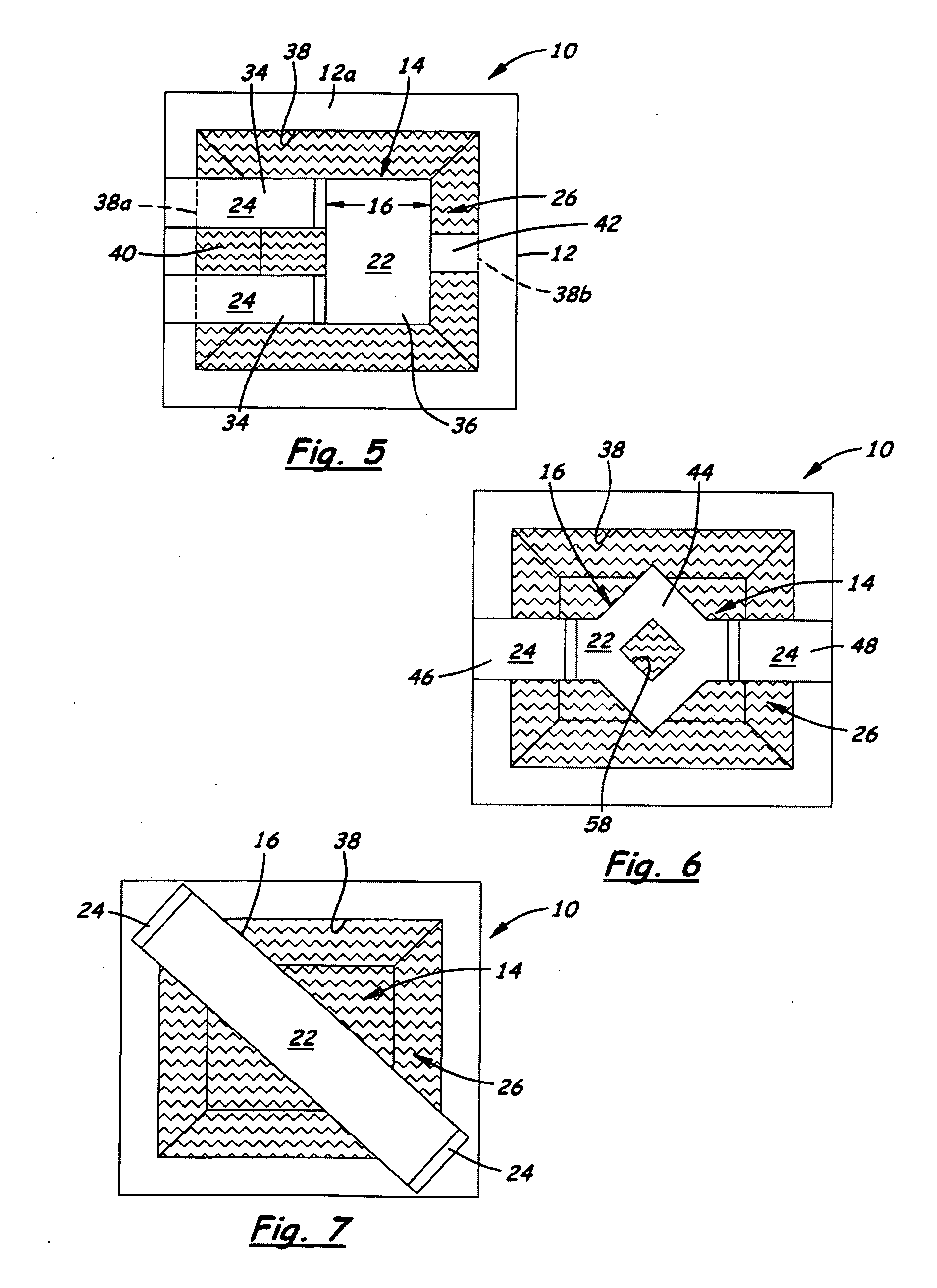
[0033]Referring now to FIG. 1-3, there is illustrated a first exemplary embodiment of a heater stack, generally designated 10, of a micro-fluid ejection device in ...


PUM


Abstract

A method for forming a floating heater element includes processing a silicon substrate to form a heater stack having the heater element on the substrate with peripheral edge portions, processing the heater stack by depositing and patterning a layer of photoresist or hard mask thereon to substantially mask the heater stack and form a trench through the photoresist or hard mask exposing a surface area of the substrate extending along the peripheral edge portions of the heater element, and processing the masked heater stack and exposed surface area of the substrate by sequentially removing the photoresist and portions of the substrate at the exposed surface area and that underlie the heater element so as to create a well in the substrate undercutting the heater element and open along the peripheral edge portions thereof, the well being capable of filling with a fluid so as to produce the floating heater element.

Description

BACKGROUND[0001]1. Field of the Invention[0002]The present invention relates generally to micro-fluid ejection devices and, more particularly, to a heater stack in a micro-fluid ejection device and a method for forming a floating electrical heater element in the heater stack.[0003]2. Description of the Related Art[0004]Micro-fluid ejection devices have had many uses for a number of years. A common use is in a thermal inkjet printhead in the form of a heater chip. In addition to the heater chip, the inkjet printhead basically includes a source of supply of ink, a nozzle plate attached to or integrated with the heater chip, and an input / output connector, such as a tape automated bond circuit, for electrically connecting the heater chip to a printer during use. The heater chip is made up of a plurality of resistive heater elements, each being part of a heater stack. The term “heater stack” generally refers to the structure associated with the thickness of the heater chip that includes ...

Claims


Application Information

Patent Timeline
Patent Type & Authority Applications(United States)
IPC IPC(8): B41J2/14H01L21/3213
CPCB41J2/1412B41J2/1601B41J2/1629B41J2/1631
Inventor GUAN, YIMINREITMEIER, ZACHARY JUSTINSULLIVAN, CARL EDMOND
Owner FUNAI ELECTRIC CO LTD
Why Eureka
Try Eureka