Microdosing Device for Dosing of Smallest Quantities of a Medium

Inactive Publication Date: 2010-07-01
ROBERT BOSCH GMBH
View PDF31 Cites 6 Cited by
  • Summary
  • Abstract
  • Description
  • Claims
  • Application Information

AI Technical Summary

Benefits of technology

[0006]By contrast, the microdosing device according to the present invention ha

Problems solved by technology

These constructions as well as others known from the related art are consequently very costly, for they frequently have a large number of layers, so that thei

Method used


Image

  • Microdosing Device for Dosing of Smallest Quantities of a Medium
  • Microdosing Device for Dosing of Smallest Quantities of a Medium
  • Microdosing Device for Dosing of Smallest Quantities of a Medium

Examples


Embodiment Construction

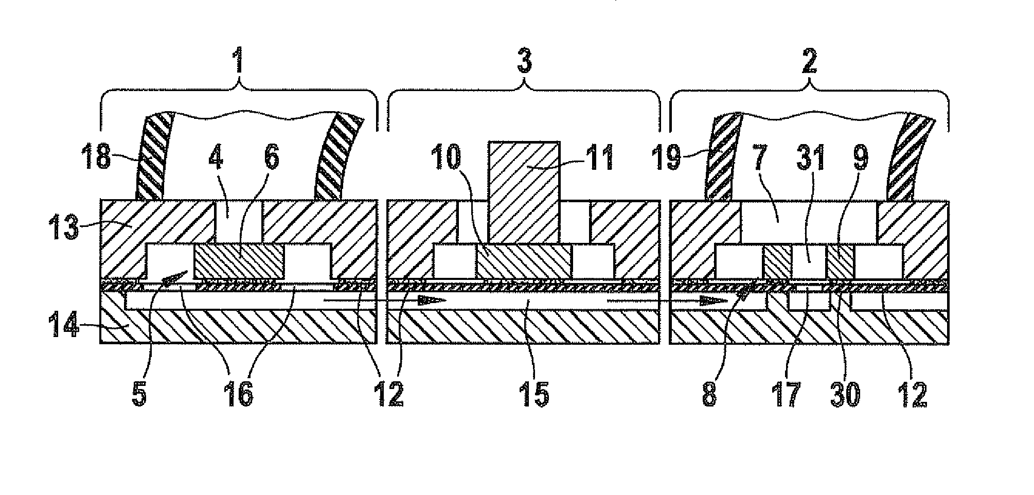
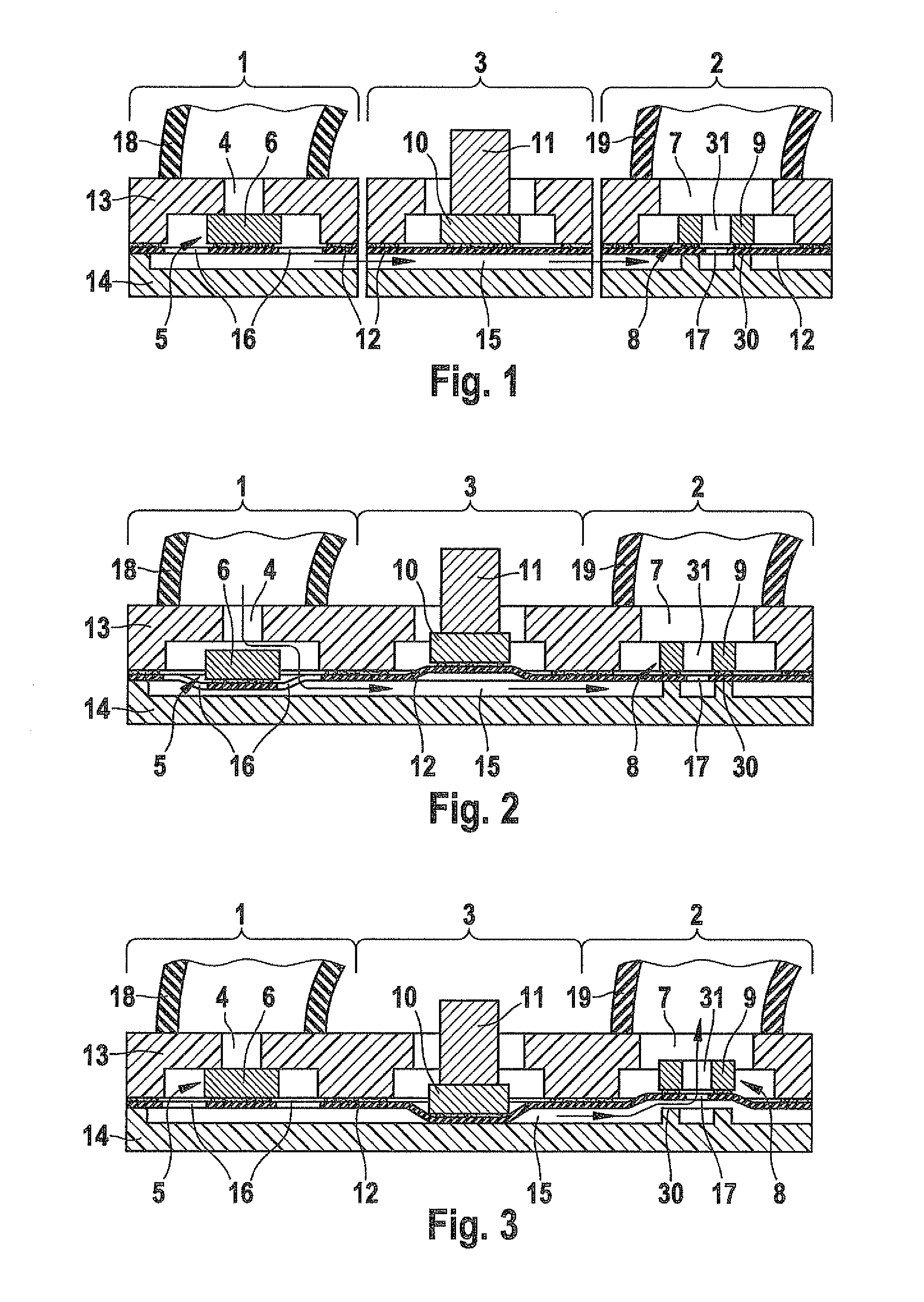
[0027]One may see in each of FIGS. 1 to 3 a schematic cross sectional representation of a microdosing device according to an exemplary embodiment of the present invention. This microdosing device is used for dosing smallest quantities of a medium, and it has an inlet device 1, an outlet device 2 and a pump device 3, which, for reasons of clarity, is shown in FIG. 1 as three functional blocks separated from one another. In actual fact, these three components of the microdosing device, according to the exemplary embodiment of the present invention, are produced directly as a coherent system on a common substrate, as will be explained below.

[0028]Inlet device 1 has an inlet opening 4 and an inlet valve 5 that has an inlet valve piston 6. In an analogous manner, outlet device 2 has an outlet opening 7, an outlet valve 8 and an outlet valve piston 9. Between inlet device 1 and outlet device 2 pump device 3 is provided, which has a pump piston 10, to which is assigned a pump actuator 11. ...


PUM


Abstract

A microdosing device for dosing smallest quantities of a medium, having an inlet device, an outlet device, a pump device and a media duct that leads from the inlet device to the outlet device, the inlet device having an inlet opening and an inlet valve having an inlet valve piston, and the outlet device having an outlet opening and an outlet valve having an outlet valve piston, and the pump device having a pump piston. The inlet valve piston, the outlet valve piston and the pump piston are situated on a common diaphragm layer. The microdosing device has the advantage that it is able to be produced in a simple and cost-effective manner.

Description

FIELD OF THE INVENTION[0001]The present invention relates to a microdosing device for the dosing of smallest quantities of a medium, having an inlet device, an outlet device and a pump device, the inlet device having an inlet opening and an inlet valve having an inlet valve piston, and the outlet device having an outlet opening and an outlet valve having an outlet valve piston, and the pump device having a pump piston.BACKGROUND INFORMATION[0002]Microdosing devices are important in various fields of application, such as in medicinal technology, and are used, for instance, for continually dispensing insulin to a diabetes patient. In this context, smallest quantities of a medium have to be dispensed in an accurately dosed manner.[0003]Various implementations of microdosing devices are known from the related art. Most of these microdosing devices use silicon bulk micromechanics for patterning silicon wafers or glass wafers which are subsequently joined on top of each other by bonding.[...

Claims


Application Information

Patent Timeline
IPC IPC(8): F04B7/04
CPCF04B43/043F04B43/028F04B43/046
Inventor REICHENBACH, RALF
Owner ROBERT BOSCH GMBH
Why Eureka
Try Eureka