Battery system with battery cells held in a stack by metal bands

a battery cell and metal band technology, applied in the field of battery systems, can solve the problems of reducing the capacity of the battery external case, increasing the internal resistance of the battery, and reducing the capacity of the battery, so as to achieve efficient cooling and high capacity.

Active Publication Date: 2010-07-01
SANYO ELECTRIC CO LTD
View PDF9 Cites 97 Cited by
  • Summary
  • Abstract
  • Description
  • Claims
  • Application Information

AI Technical Summary

Benefits of technology

[0013]The battery system described above has the characteristic that while the metal bands are put in close proximity to battery cell outer side-walls, short circuits between battery cells and the metal bands can be reliably prevented. Further, the insulating walls, which electrically isolate the metal bands and the battery cell outer side-walls, are formed as a single-piece with the plastic insulating separators, which electrically isolate adjacent battery cells. Therefore, the battery system described above has the characteristic that the insulating walls can be disposed in accurate locations without shifting position via the insulating separators, and the battery cells can be reliably insulated from the metal bands.
[0014]In the battery system of the present invention, an insulating separator 15 can be provided with insulating walls 15C formed as a single-piece with the insulating plate section 15 and connected to the edges on both sides of the insulating plate section 15X. Battery cells 1 can fit between the insulating walls 15C on both sides of the insulating plate section 15X. By disposing battery cells between the insulating walls of this battery system, battery cells can be stacked with insulating separators in specified locations without shifting position. Consequently, the battery cells can be stacked via the insulating separators while preventing lateral position shift of the battery cells.
[0015]In the battery system of the present invention, an insulating separator 15 can be provided with insulating walls 15C formed as a single-piece with the insulating plate section 15 and connected to the top and bottom of the edges on both sides of the insulating plate section 15X. Top and bottom insulating walls 15C connect to vertical sections 15y that cover battery cell 1 outer side-walls. Horizontal sections 15x that cover battery cell 1 upper and lower surfaces are formed as a single-piece, and battery cells 1 can fit inside the vertical sections 15y and horizontal sections 15x. By disposing battery cells inside the insulating walls of this battery system, battery cells can be stacked with insulating separators while preventing battery cell lateral and vertical position shift. Consequently, the battery cells can be stacked via the insulating separators while preventing lateral or vertical position shift.
[0017]In the battery system of the present invention, air passage-way slits 77 can be established between the insulating walls 75C of adjacently stacked insulating separators 75. In this battery system, battery cell external cases can be efficiently cooled via the air passage-way slits established between insulating walls. This is because external case surfaces exposed through the air passage-way slits can be directly cooled by a cooling medium such as a cooling gas.
[0018]The battery cells 1 of the battery system of the present invention can be lithium ion batteries. This battery system has the characteristics that the outline can be compact, and while light-weight, the capacity can be high. The above and further objects of the present invention as well as the features thereof will become more apparent from the following detailed description to be made in conjunction with the accompanying drawings.

Problems solved by technology

A battery system with this structure has the drawback that depending on operating conditions, battery performance can deteriorate.
In particular, this type of battery system has the drawback that since lithium ion batteries are used as the rectangular batteries, depending on operating conditions, battery internal resistance can increase and reduce output.
This is because the lateral protrusions can easily deform and expansion of battery external cases cannot be reliably prevented.
Since the gap between positive and negative electrodes is narrow to reduce internal resistance, the internal resistance can become large even if electrode expansion results in only a small increase in the gap between electrodes.
Since a battery system with a plurality of stacked rectangular batteries is used in applications demanding high output such as in an automobile, reduction in output is a serious drawback.
Further, the battery system of FIG. 1 has the drawback that if the rectangular batteries 901 expand, the bolts 906 can contact the sides of the rectangular batteries 901.
Consequently, if a bolt contacts a plurality of rectangular battery external cases, short circuit current flow will detrimentally affect the batteries and compromise safety.
In a battery system of this structure, the metal bars can easily deform with rectangular battery expansion, and it is difficult to reliably prevent rectangular battery expansion and battery performance degradation.
This battery system has the drawback that since the metal bars are attached by welding, it is difficult to hold the rectangular batteries with a properly adjusted amount of compression.
However, this battery system has the drawback that the metal bands can easily contact and short circuit battery cell outer side-walls.
Further, if an external case contacts a metal band, it can cause leakage current.

Method used


Image

  • Battery system with battery cells held in a stack by metal bands
  • Battery system with battery cells held in a stack by metal bands
  • Battery system with battery cells held in a stack by metal bands

Examples


Embodiment Construction

)

[0032]Although the battery system of the present invention is not restricted to a specific application, it is primarily suitable as a car power source apparatus for use on-board an electrically driven vehicle such as a hybrid car or electric automobile to supply power to a driving motor.

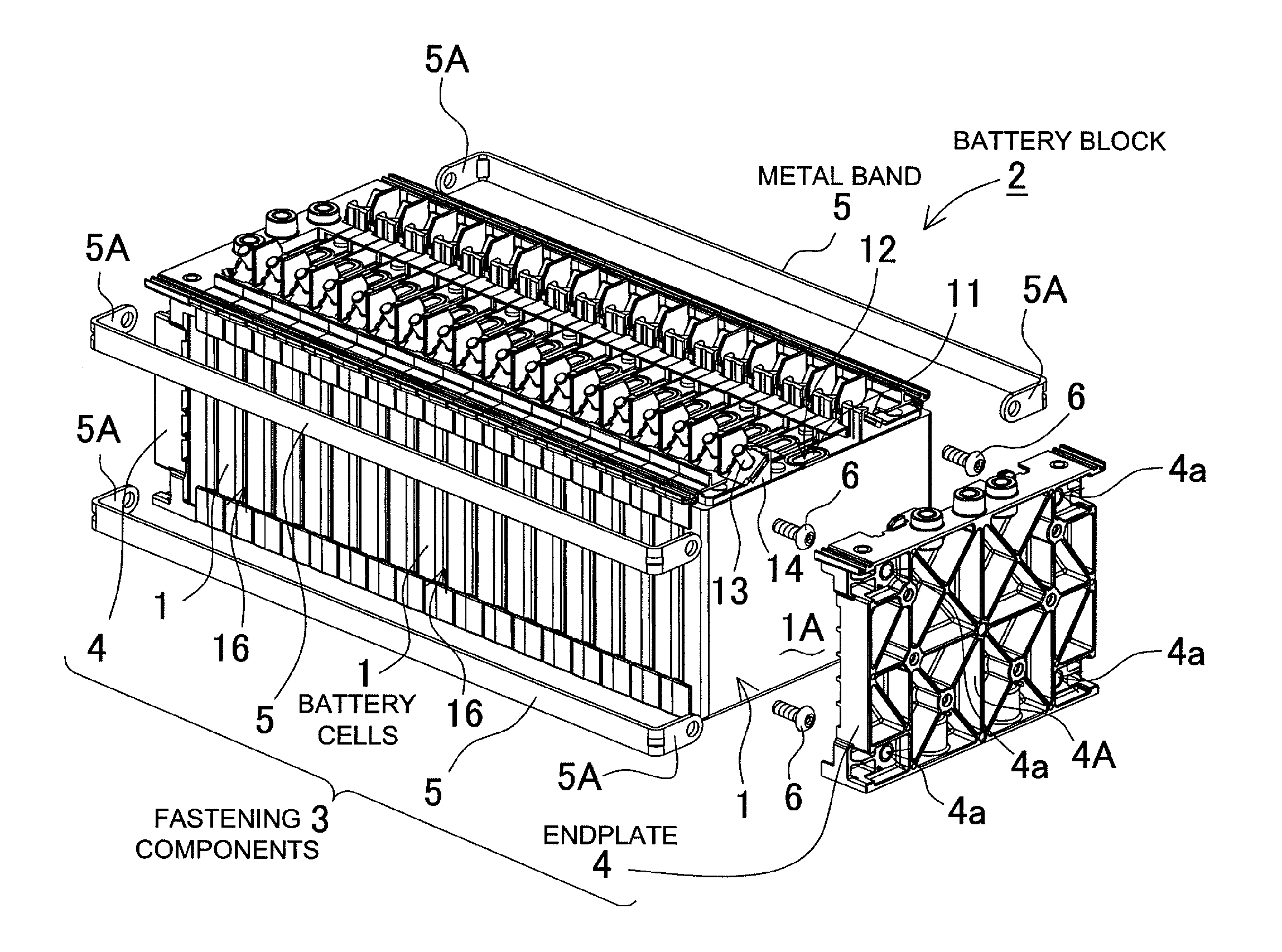
[0033]FIGS. 3-8 show battery systems for embodiments of the present invention. FIGS. 3 and 4 show a car power source apparatus provided with four battery system units, and FIGS. 5-8 show the battery system employed in that power source apparatus.

[0034]The battery system shown in these figures is provided with a battery block 2 having a plurality of stacked battery cells 1 that are rectangular batteries, and fastening components 3 that hold the battery cells 1 of the battery block 2.

[0035]The rectangular battery cells 1 are lithium ion batteries. However, rectangular battery cells are not limited to lithium ion batteries and any rechargeable batteries, such as nickel hydride batteries can be used. A ...


PUM

PropertyMeasurementUnit
thicknessaaaaaaaaaa
thicknessaaaaaaaaaa
thicknessaaaaaaaaaa

Abstract

The battery system has a battery block 2 with a plurality of battery cells 1 that are rectangular batteries stacked with intervening insulating separators 15, and that battery block 2 is held by fastening components 3. The fastening components 3 are provided with a pair of endplates 4 disposed at the ends of the stacked battery cells 1, and metal bands 5 on both sides of the battery block 2 connected at both ends to the endplates 4. An insulating separator 15 has an insulating plate section 15X, which intervenes between adjacent battery cells 1, and insulating walls 15C, which cover both battery cell 1 side-walls, formed from plastic as a single-piece. In this battery system, insulating plate sections 15X are sandwiched between battery cells 1, and the insulating walls 15C are disposed between battery cell outer side-walls and metal bands to insulate the battery cells from the metal bands.

Description

BACKGROUND OF THE INVENTION[0001]1. Field of the Invention[0002]The present invention relates to a battery system with a plurality of battery cells, which are rectangular batteries, held in a stack by fastening components.[0003]2. Description of the Related Art[0004]As shown in FIG. 1, a battery system with a plurality of stacked battery cells, which are rectangular batteries, has a pair of endplates 905 connected by bolts 906 to dispose batteries 901 in a stack between the endplates 905. (Refer to Japanese Laid-Open Patent Publication No. H03-32364A (1991).) In the battery system cited in JP H03-32364A as shown in FIG. 1, the endplates 905 are provided with lateral protrusions 908 on both sides for insertion and connection of the bolts 906. The bolts 906 are inserted through the lateral protrusions 908 and nuts 907 are threaded onto the ends to hold the endplates 905 in place. A battery system with this structure has the drawback that depending on operating conditions, battery perf...

Claims


Application Information

Patent Timeline
Patent Type & Authority Applications(United States)
IPC IPC(8): H01M2/10H01M50/209H01M50/233H01M50/264H01M50/291H01M50/293
CPCH01M2/1077H01M2/1083H01M2/1094H01M2/1223H01M10/0525Y02E60/10H01M50/24H01M50/317H01M50/293H01M50/233H01M50/209H01M50/264H01M50/291
Inventor OKADA, WATARUNAKAMURA, SHINSUKEOHMURA, TOMOYUKIWAKABAYASHI, AKINOBU
Owner SANYO ELECTRIC CO LTD
Why Eureka
Try Eureka