Portable terminal, portable apparatus and supply power control method

Inactive Publication Date: 2010-07-01
KYOCERA CORP
View PDF9 Cites 26 Cited by
  • Summary
  • Abstract
  • Description
  • Claims
  • Application Information

AI Technical Summary

Problems solved by technology

However, in recent years, with the advances in technology, the various batteries stated above have are experiencing high functionality wherein the electric power consumption of portable terminals is increasing rapidly due to continuous display of

Method used


Image

  • Portable terminal, portable apparatus and supply power control method
  • Portable terminal, portable apparatus and supply power control method
  • Portable terminal, portable apparatus and supply power control method

Examples


first embodiment

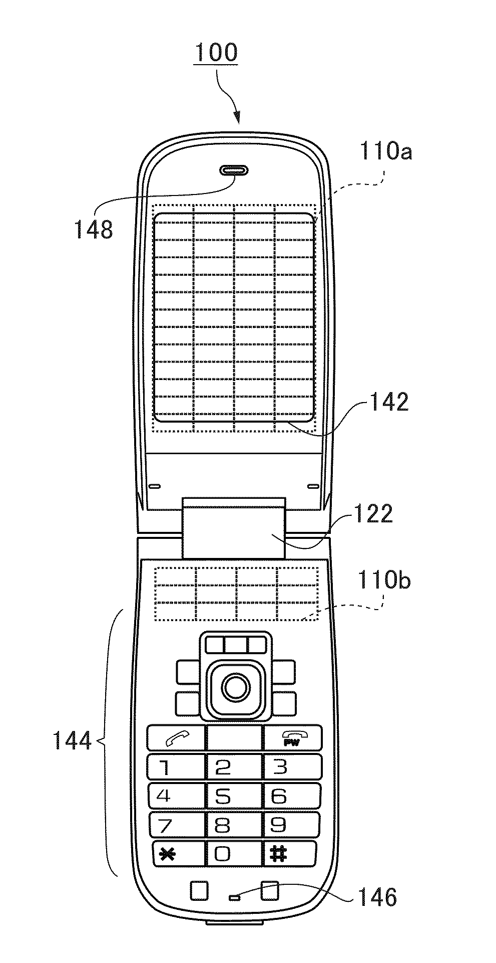
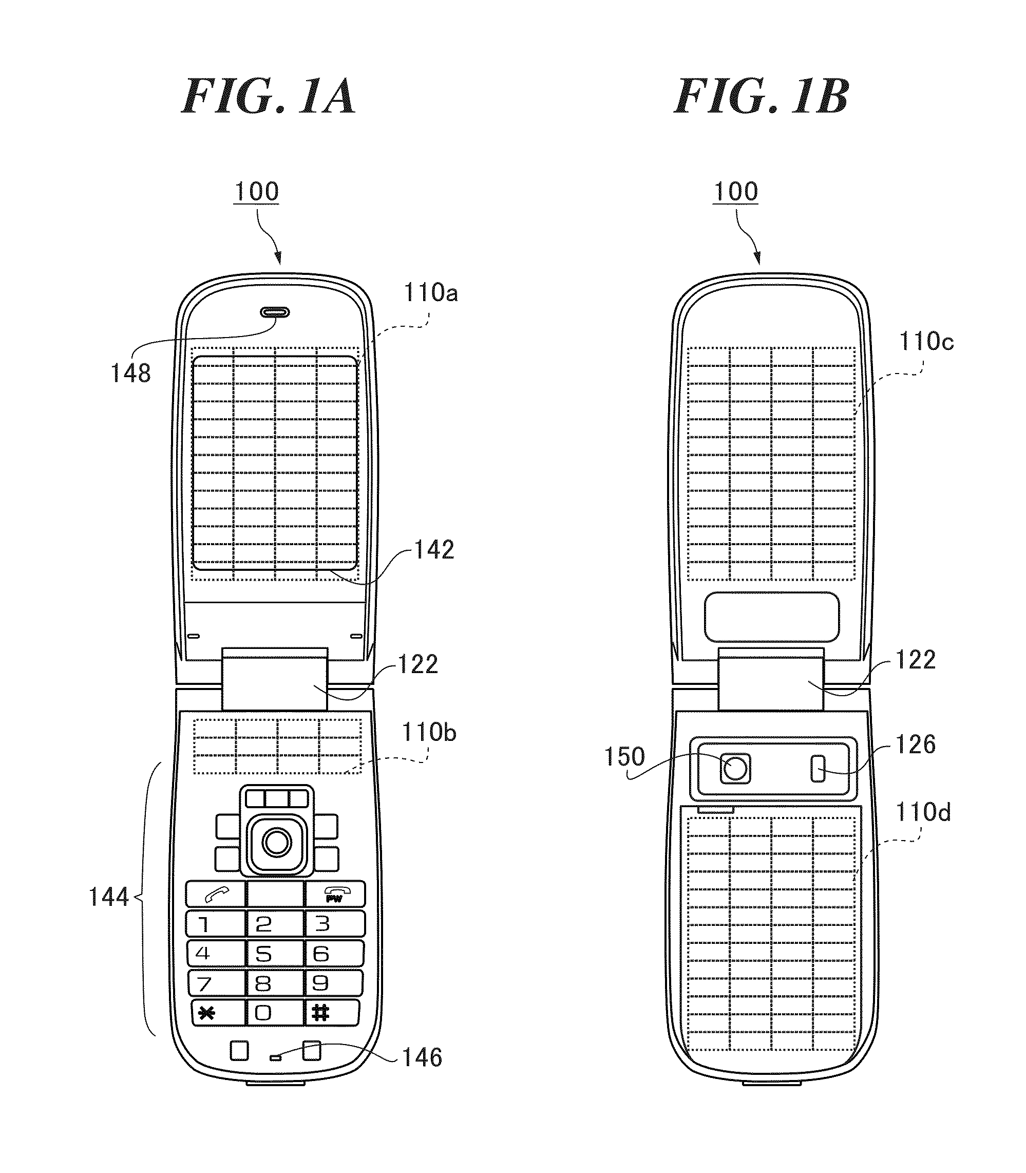
[0056]Generally, in a cellular phone mounted with a solar cell, the solar cell and an electric power control part which controls the electric power of the cell act together as a pair of electronic circuits. So, the electric power control part always operates with the solar cell, even when the amount of light received by the solar cell is small because of a place where the cellular phone is stored and of a state how the cellular phone is grasped. In order to control electric power generated by the solar cell, the electric power control part sometimes consumes electric power more than that generated by the solar cell. In this case the solar cell is insufficient as an auxiliary battery and therefore electric power consumption is increased.

[0057]A portable terminal and a method for controlling electric power supply according to the present embodiment can increase the probability of receiving light by a solar cell module and maximize the function of a solar cell module as an auxiliary ba...

second embodiment

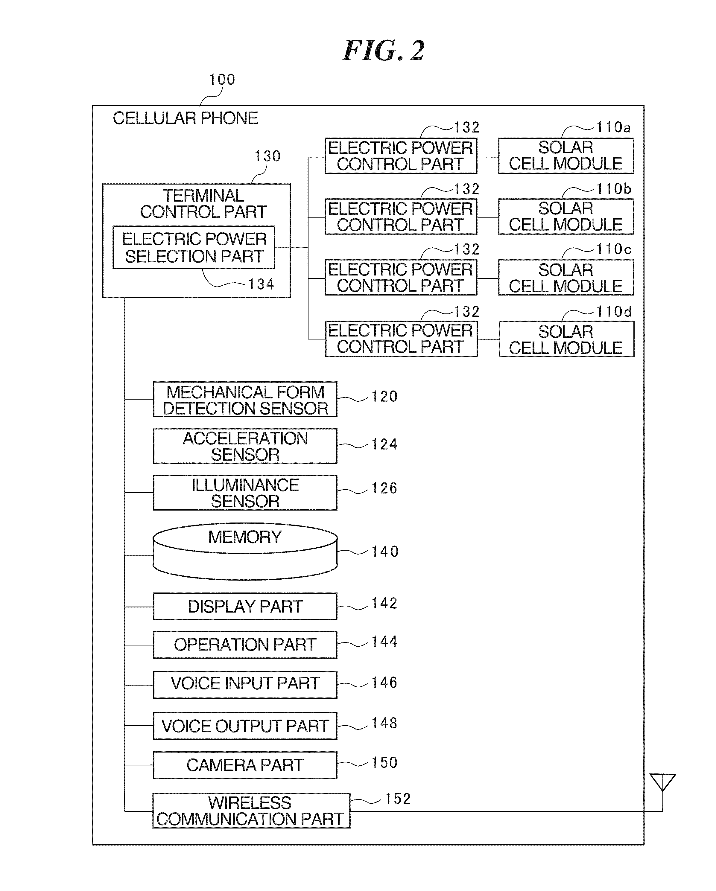
[0097]The portable terminal according to the first embodiment uses the state detection part in order to detect a solar cell module arranged on a surface that is not exposed to a light source. However, it is also possible to determine the necessity of each electric power control part by once turning on the each electric power control part and by measuring the amount of electric power generated thereby. A second embodiment of the portable terminal will be explained below, as it is adopted to do the above stated method. Here, a cellular phone is used as a portable terminal for the purposes of explanation in the following. However, the portable terminal is not limited to a cellular phone but may be various ones such as a PHS or PDA.

(Cellular Phone 200)

[0098]FIG. 7 is a function block diagram which shows the approximate functions of a cellular phone 200 according to the second embodiment. The cellular phone 200 is a folding type cellular phone and is comprised of four solar cell modules ...

third embodiment

[0107]A portable terminal is used as an example in the embodiments stated above, however, the present invention can also be applied to a portable apparatus. In the present embodiment, a portable apparatus is assumed to be an electronic apparatus which is comparatively larger than a portable terminal, can be carried and operated by a battery installed within the apparatus. Below, a portable apparatus according to the present embodiment is exemplified.

[0108]FIG. 9 is a diagram which shows an example of a portable apparatus related to a third embodiment. As the portable apparatus, FIG. 9A shows a note type computer, FIG. 9B shows a tablet type computer and FIG. 9C shows a mobile game device. It is possible to arrange solar cell modules in a plurality of arbitrary places (surfaces) in the portable apparatus shown in FIGS. 9A to 9C. In addition, it is also possible to apply the present embodiment to portable apparatus, other than those shown in FIGS. 9A to 9C, such as a mobile metal dete...


PUM


Abstract

The cellular phone 100 according to the present invention comprises a plurality of solar cell modules 110 arranged on different surfaces of a casing, a plurality of electric power control parts 132 connected to each of said plurality of solar cell modules 110, a mechanical form detection sensor 120 as a state detection part for detecting a state of said cellular phone 100, and an electric power selection part 134 (FIG. 1).

Description

TECHNICAL FIELD[0001]The present invention relates to a portable terminal mounted with a plurality of solar cell modules, portable apparatus and a method for controlling electric power supply used by the portable terminal and portable apparatus.[0002]Various portable terminals have been provided in recently such as PHS (Persona Handy—Phone System), cellular phones, and PDA (Persona Digital Assistant) etc. These portable terminals are equipped with a display part such as LCD for a display interface, and with a control part such as a plurality of switches (keys) and touch panels, so that a user can easily refer to and input information while outdoors.[0003]Conventionally, portable terminals obtain their electric power for consumption from a battery. Generally, secondary batteries such as a lithium battery, nickel cadmium battery, or nickel hydride battery are adopted as the above stated battery.[0004]However, in recent years, with the advances in technology, the various batteries stat...

Claims


Application Information

Patent Timeline
IPC IPC(8): H04B1/38H01L31/042H02J7/35H02S40/36H04M1/00H04M1/02H04M1/21H04M1/73H04W88/02
CPCH02J7/355H04M1/0214H04M1/0233H04M1/0235Y10T307/685H04W52/028H04W52/0296Y02D70/164H04M2250/12H02J7/35Y02E10/50Y02D30/70
Inventor MORICHI, YOSHIHISA
Owner KYOCERA CORP
Why Eureka
Try Eureka