
Tissue classifying apparatus

a technology of tissue classification and apparatus, applied in the field of tissue treatment system, can solve the problems of tissue damage, tissue ablation, radiation power that might damage the tissue being measured, etc., and achieve the effect of reducing the cost of components and overall system development costs, reducing or overcoming this limitation requirement, and facilitating the setting up of high q cavities and structures

Inactive Publication Date: 2010-07-01
MEDICAL DEVICE INNOVATIONS
View PDF3 Cites 43 Cited by
  • Summary
  • Abstract
  • Description
  • Claims
  • Application Information

AI Technical Summary

Benefits of technology

"The present invention proposes a solution to the problem of drift in the measurement signal caused by temperature variations and other changes in the microwave components or devices in the apparatus. The solution involves providing a forward reference signal to the detector, which is derived from the same source as the reflected signal. The detector is then able to compare the reflected signal with the reference signal and cancel out any drift. This improves the accuracy of the measured results. However, the inventors have discovered that the use of a circulator to isolate the reference signal may cause drift in the measured results due to changes in the DC power supply. To address this problem, the invention proposes a solution that involves regularly switching the detector input between the reference and reflected signals, and measuring the difference in magnitude and phase between the two signals. This difference is related to the reflection coefficient caused by the tissue impedance, and the tissue classifier is able to calculate the complex impedance of the tissue using the measured difference. The circulator acts to isolate the reference signal from the reflected signal, and the detector is able to compare the reflected signal with the reference signal and cancel out any drift."

Problems solved by technology

The inventors realised that there was a potential problem with coupling the measurement signal from the ablation line.
It was identified that there is a risk that the delivered radiation might be powerful enough to damage the tissue being measured, i.e. the measurement signal may cause tissue ablation, e.g. it was discovered that power levels of around 1 W generated at the frequency of interest can produce tissue damage.
However, the inventors have discovered that drift occurs in the phase and magnitude of the delivered signal due to temperature variations and other changes in the microwave components or other components or devices in the apparatus.
This drift occurs during a time period in which the apparatus would typically be used and can therefore lead to inaccuracies in the measured results.

Method used


Image

  • Tissue classifying apparatus
  • Tissue classifying apparatus
  • Tissue classifying apparatus

Examples


Embodiment Construction

; FURTHER OPTIONS AND PREFERENCES

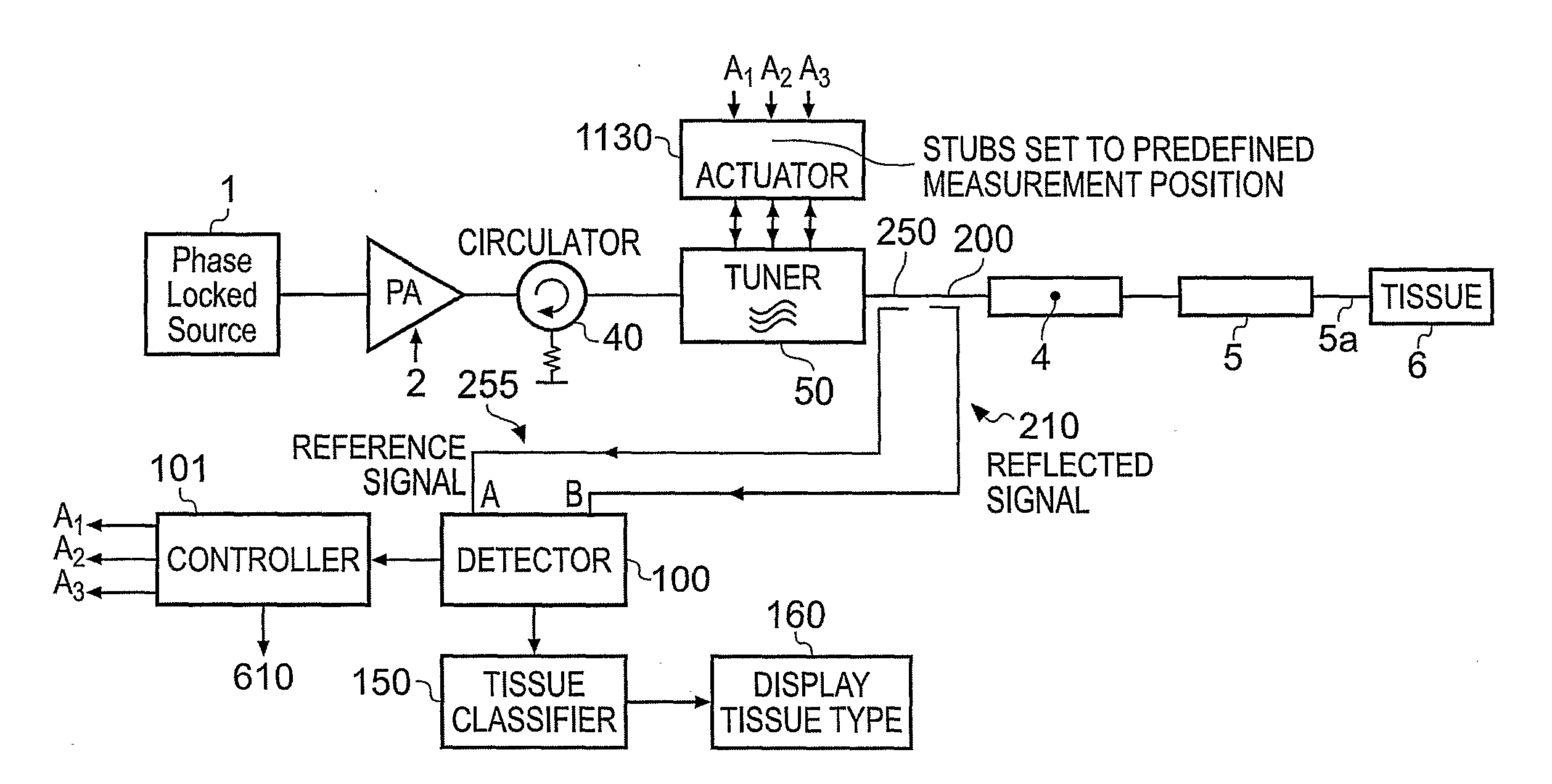
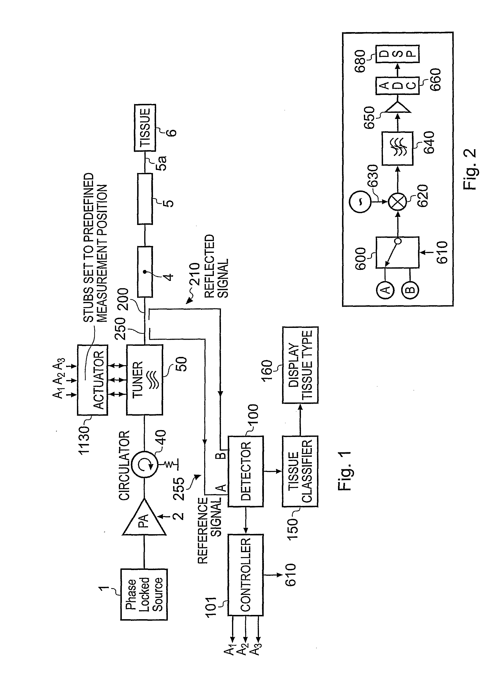
[0035]FIG. 3 shows a diagram of an electrosurgical system that is suitable for using with the invention. It includes two treatment channels (an ablation channel and a measurement channel) which are described in detail below.

[0036]Both channels begin at a microwave source 108 and include treatment antenna (probe) 116. In the ablation channel, a primary frequency source 161 is used to generate a low power signal at a predetermined frequency, a driver amplifier 110 to amplify the output signal level produced by the primary frequency source 161, and a power amplifier 112 to amplify the signal produced by the driver amplifier 110 to a level that may cause controlled tissue destruction. The output from the power amplifier 112 is connected to a microwave circulator 114 which is used to protect the output transistors contained within power amplifier 112 from excessive amounts of reflected power caused by an impedance mismatch at the distal end of the treatme...


PUM


Abstract

Tissue classifying apparatus in which forward microwave radiation (e.g. having a frequency 500 MHz to 60 GHz) is supplied from a source (108) along a first transmission path to a probe (116) which delivers it into tissue to be classified. The probe (116) receives reflected radiation from the tissue. The reflected radiation is delivered to a detector (178) along a second transmission path via a circulator (198) which isolates the forward radiation from the second transmission path. The detector has a input which is switchable between the reflected radiation from the second transmission path and a reference signal derived from the forward radiation, wherein detected magnitude and phase information of the reflected radiation to classify the tissue can be compensated for drift in magnitude and phase of the forward radiation by comparison with detected magnitude and phase information of the reference signal.

Description

FIELD OF THE INVENTION[0001]The invention relates to the treatment of biological tissue using microwave radiation. In particular, the invention relates to a tissue treatment system capable of measuring tissue properties using microwave radiation delivered from an antenna probe.BACKGROUND TO THE INVENTION[0002]An electrosurgical system that is arranged to controllably ablate biological tissue (e.g. a tumour) and / or measure information concerning the tumour and surrounding healthy tissue is known. Such a system may use two channels: a first channel to perform controlled tissue ablation, and a second channel to perform sensitive tissue state (dielectric) measurements. The general principles relating to the operation of such a system are disclosed in WO2004 / 047659 and WO2005 / 115235.[0003]FIG. 1 shows a schematic diagram of the apparatus disclosed in WO2005 / 115235. The apparatus has a stable phase locked source of microwave radiation 1 connected to a probe 5 configured to direct the micr...

Claims


Application Information

Patent Timeline
Patent Type & Authority Applications(United States)
IPC IPC(8): A61B18/18A61B5/05
CPCA61B5/05A61B5/0507A61B5/7264A61B18/18A61B18/1815G16H50/20
Inventor HANCOCK, CHRISTOPHER PAULBISHOP, JOHNBOOTON, MARTIN WYNFORD
Owner MEDICAL DEVICE INNOVATIONS
Learn More