
Polarization control system and display device

Active Publication Date: 2010-07-08
LG ELECTRONICS INC +1
View PDF10 Cites 22 Cited by
  • Summary
  • Abstract
  • Description
  • Claims
  • Application Information

AI Technical Summary

Benefits of technology

[0065]The polarization control system of the present invention includes an E-type polarizer and therefore can provide excellent dark state at a wide azimuth and viewing angle. Further, the polarization control system includes a viewing angle control element for controlling a traveling direction of light which has passed through the E-type polarizer and therefore can provide excellent bright state at a wide azimuth and viewing angle.BEST MODES FOR CARRYING OUT THE INVENTIONEmbodiment
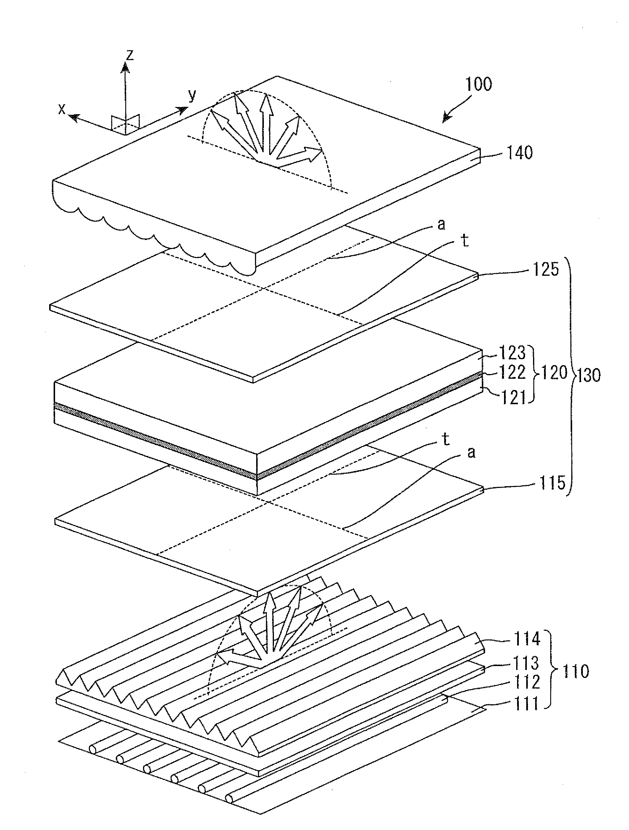
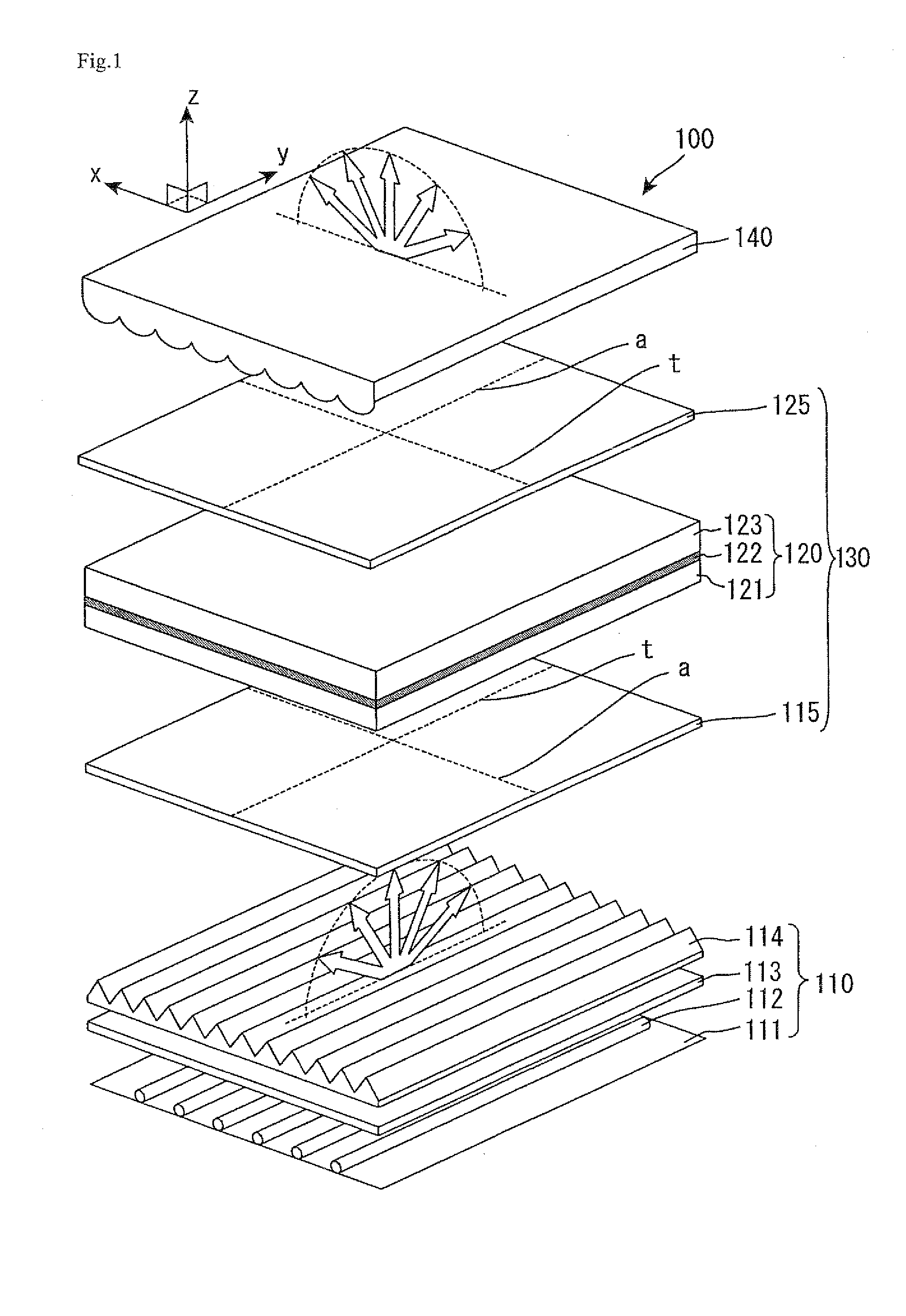
[0066]FIG. 1 is a perspective view schematically showing a liquid crystal display device in accordance with Embodiments of the present invention.
[0067]The liquid crystal display device in accordance with the present Embodiments has a structure in which diffuse illumination means (light source device) 110; a liquid crystal display panel 130 including an O-type polarizer 115, a liquid crystal cell 120, and an E-type polarizer 125; and a viewing angle control film (viewing angle control element) 140 are stacked in this order, as shown in FIG. 1. A liquid crystal display device 100 in accordance with the present Embodiments can be prepared by a common method. That is, the liquid crystal display device 100 can be prepared in the following manner: the diffuse illumination means 110, the liquid crystal display panel 130, the viewing angle control film 140, and if necessary, a component such as a retardation film are appropriately assembled, and thereinto, a driving circuit is incorporated.
[0068]The configuration of the liquid crystal display device of the present invention is not especially limited except that an E-type polarizer is used as at least one of the pair of polarizers and the viewing angle control film is used. A configuration of a common liquid crystal display device may be applied to the liquid crystal display device of the present invention. For example, according to the present Embodiments, the O-type polarizer 115 is arranged on a back surface side of the liquid crystal cell 120, and the E-type polarizer 125 is arranged on an observation surface side of the liquid crystal cell 120. However, the E-type polarizer 125 may be arranged on the back surface side of the liquid crystal cell 120, and the O-type polarizer 115 may be arranged on the observation surface side of the liquid crystal cell 120. According to the present Embodiment, the viewing angle control film 140 is not a member constituting the liquid crystal display panel 130 (is not a part of the liquid crystal display panel 130), but may be such a member constituting the liquid crystal display panel 130 (may be a part of the liquid crystal display panel 130). For example, the viewing angle control film 140 may be integrated with the E-type polarizer 125.
[0070]The diffuse illumination means 110 is composed of a light reflective sheet 111, a plurality of light sources 112, a light diffuser 113, and directivity control means (member) 114. Common light sources can be used as the light sources 112. For example, fluorescent tubes, such as a cold cathode fluorescent tube (CCFL) and a hot cathode fluorescent tube (HCFL), and a light emitting diode (LED), and the like may be used. As the directivity control means 114, a prism film which has a light condensing function (product of Sumitomo 3M Ltd., trade name; Brightness Enhancement Film BEF) and an anisotropic diffusion sheet whose diffusion degree varies depending on a direction (for example, refer to Japanese Kokai Publication No. Hei-04-314522) can be used in order to effectively exhibit the effects of the present invention.
[0071]According to the diffusion illumination means 110 in the present Embodiment, as shown in FIG. 1, it is preferable that an amount of light which is emitted by the diffusion illumination means 110 into an azimuth parallel to a y axis azimuth is larger than an amount of light which is emitted by the diffusion illumination means 110 into an azimuth parallel to an x axis azimuth. That is, the plurality of the light sources 112 output diffusion light with low directivity, in which a luminance of the diffusion light less depends on an angle, but it is preferable that the directivity control means 114 provides the diffusion light with the above-mentioned directivity. This is because the E-type polarizer 125 absorbs incident light from an oblique direction at an azimuth parallel to a transmission axis t azimuth of the E-type polarizer 125 more than incident light from an oblique direction at an azimuth parallel to a transmission axis t azimuth of the O-type polarizer 115. Accordingly, in order to reduce the amount of light which enters the E-type polarizer 125 at an azimuth parallel to the transmission axis t azimuth of the E-type polarizer 125, it is advantageous in terms of light use efficiency that the diffusion illumination means 110 is adjusted in such a way that an amount of light emitted into such an azimuth and that a relative amount of light emitted into an azimuth parallel to an absorption axis a azimuth of the E-type polarizer 125 is increased. Further, the diffusion illumination means 110 and the viewing angle control film 140 are optimally designed together, which can optionally adjust an intensity distribution of light which is finally outputted to the observation surface side.

Problems solved by technology

However, if the E-type polarizer is used, Parallel-Nicol state (bright state) can not be provided at a wider azimuth and viewing angle.
Accordingly, excellent bright state cannot be provided at a wider azimuth or viewing angle.

Method used


Image

  • Polarization control system and display device
  • Polarization control system and display device
  • Polarization control system and display device

Examples


embodiment 1

[0079]A liquid crystal cell was prepared by separating polarizers and retardation films arranged on both sides (observation surface side and the back surface side) of a liquid crystal display panel in a commercially available liquid crystal display device in normally black VA mode (product of Sharp Corp., trade name: LC20AX-5). Then, a triacetyl cellulose film (product of FUJIFILM Corp., trade name: TD-80U) was used as a base film, and thereon, an aqueous solution of lyotropic liquid crystal containing 16.7% by weight of a dichroic pigment on the solid content basis (product of Optiva, Inc., trade name: LC polarizer) was applied on the base film to have a thickness of 4 μm with a wire bar. Then, the coated liquid was dried at 40° C. to provide an E-type polarizer. Thus-prepared E-type polarizer was arranged on the back surface side of the liquid crystal cell in such a way that the base film surface was not on the liquid crystal cell side (the coated surface is on the side of the liq...

embodiment 2

[0085]A liquid crystal display device in the present Embodiment has the same configuration as in Embodiment 1 except that the following viewing angle control element was used. A microlens array sheet (refer to Embodiment 1 in Japanese Kokai Publication No. Hei-05-249453) which includes convex lenses (material: UV-curable acrylic resin, a regular hexagonal bottom surface having a scattering intensity of 15°, and an arrangement pitch of the lenses: 64 μm) on one surface of a transparent base film (material: polyester, thickness: 188 μm), was arranged in such a way that: the surface where the convex lenses are formed is on the liquid crystal cell side and the other surface is on the observation surface side; and that a diffusion major axis azimuth of the sheet is parallel to a transmission axis azimuth in the plane of the O-type polarizer (an absorption axis azimuth in the plane of the E-type polarizer).

embodiment 3

[0086]A liquid crystal display device in the present Embodiment has the same configuration as in Embodiment 2, except that as the viewing angle control element, a light diffraction film (product of Sumitomo Chemical Co., Ltd., trade name: LUMISTY, product number: MFX-1515) was arranged in such a way that an azimuth where opaque state is observed is parallel to a transmission axis azimuth in the plane of the O-type polarizer (an absorption axis azimuth in the plane of the E-type polarizer).


PUM


Abstract

The present invention provides a polarization control system which includes an E-type polarizer and therefore can provide excellent dark state at a wide azimuth and viewing angle. Further, the polarization control system includes a viewing angle control element for controlling a traveling direction of light which has passed through the E-type polarizer and therefore can provide excellent bright state at a wide azimuth and viewing angle. The present invention further provides a display device including such a polarization control system. The polarization control system of the present invention is a polarization control system including a plurality of polarizer, wherein the polarization control system includes an E-type polarizer and a viewing angle control element, and the viewing angle control element controls a traveling direction of light which has passed through the E-type polarizer.

Description

TECHNICAL FIELD[0001]The present invention relates to a polarization control system and a display device. More specifically, the present invention relates to a polarization control system suitably used in a display device such as a liquid crystal display device and the like. The present invention further relates to a display device.BACKGROUND ART[0002]There are various types (generally, called “display mode”) of the liquid crystal display device. A display mode in which a liquid crystal cell is arranged between a pair of polarizers disposed in Cross Nicol arrangement is the most common mode. Such a liquid crystal display device provides black display by disposing a pair of polarizers substantially in Cross-Nicol state (dark state) in the following system. Liquid crystal molecules are aligned substantially vertically to substrates such that the liquid crystal cell has a retardation, or alternatively, the liquid crystal cell has a retardation, but an optic axis azimuth of the cell is ...

Claims


Application Information

Patent Timeline
IPC IPC(8): G02F1/1335G02B5/30
CPCG02B3/005G02B5/3033G02F1/133526G02F1/133528G02F2001/133531G02F2001/133607G02F2413/11G02F2413/12G02F1/133531G02F1/133607G02F1/133634
Inventor SAKAI, AKIRA
Owner LG ELECTRONICS INC
Learn More