Filter circuit

a filter circuit and filter technology, applied in the field of filter circuits, can solve the problems of difficult generation of canceling signals that can completely cancel out a noise heard through user's ears, low frequency of audio signals to be processed thereby, and difficulty in applicability of filter circuits listed abov

Inactive Publication Date: 2010-07-08
AUDIO-TECHNICA
View PDF8 Cites 26 Cited by
  • Summary
  • Abstract
  • Description
  • Claims
  • Application Information

AI Technical Summary

Benefits of technology

[0015]In view of the above, an object of the present invention is to provide a filter circuit that allows a user to utilize its characteristic in which, when a frequency of an input signal becomes higher, a phase advance of the output signal relative to the input signal increases.
[0023]The present invention provides a filter circuit capable of correcting a conventional phase characteristic of an acoustic system in which a phase is displaced according to frequency levels, thereby enabling a natural audio processing.

Problems solved by technology

All the filter circuits listed above are difficult to be formed with an applicative coil because frequencies of audio signals to be processed thereby are low.
Therefore, a canceling signal that can completely cancel out a noise heard through user's ears is difficult to be generated.
Actually, generation of such canceling signal is difficult.
Thus, the filter circuit cannot be expected to correct the phase displacement.
However, as described above, use of a plurality of the conventional filter circuits limits the frequency band within which the noise can be canceled out.
However, a filter circuit has not been available that allows the user to utilize its characteristic in which, when the frequency of the input signal becomes higher, the phase advance of the output signal relative to the input signal increases.

Method used


Image

  • Filter circuit
  • Filter circuit
  • Filter circuit

Examples


first embodiment

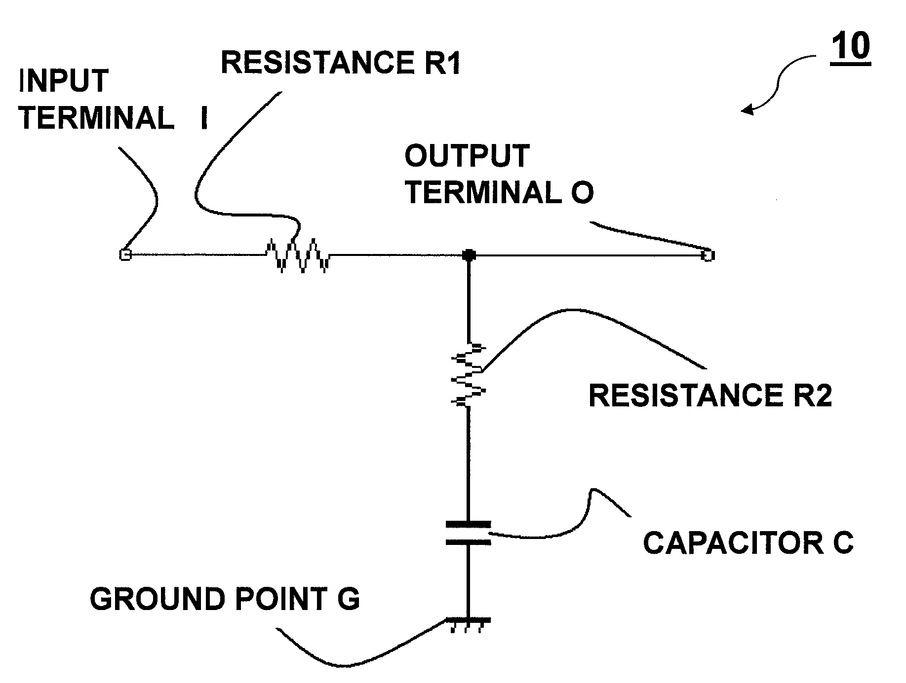
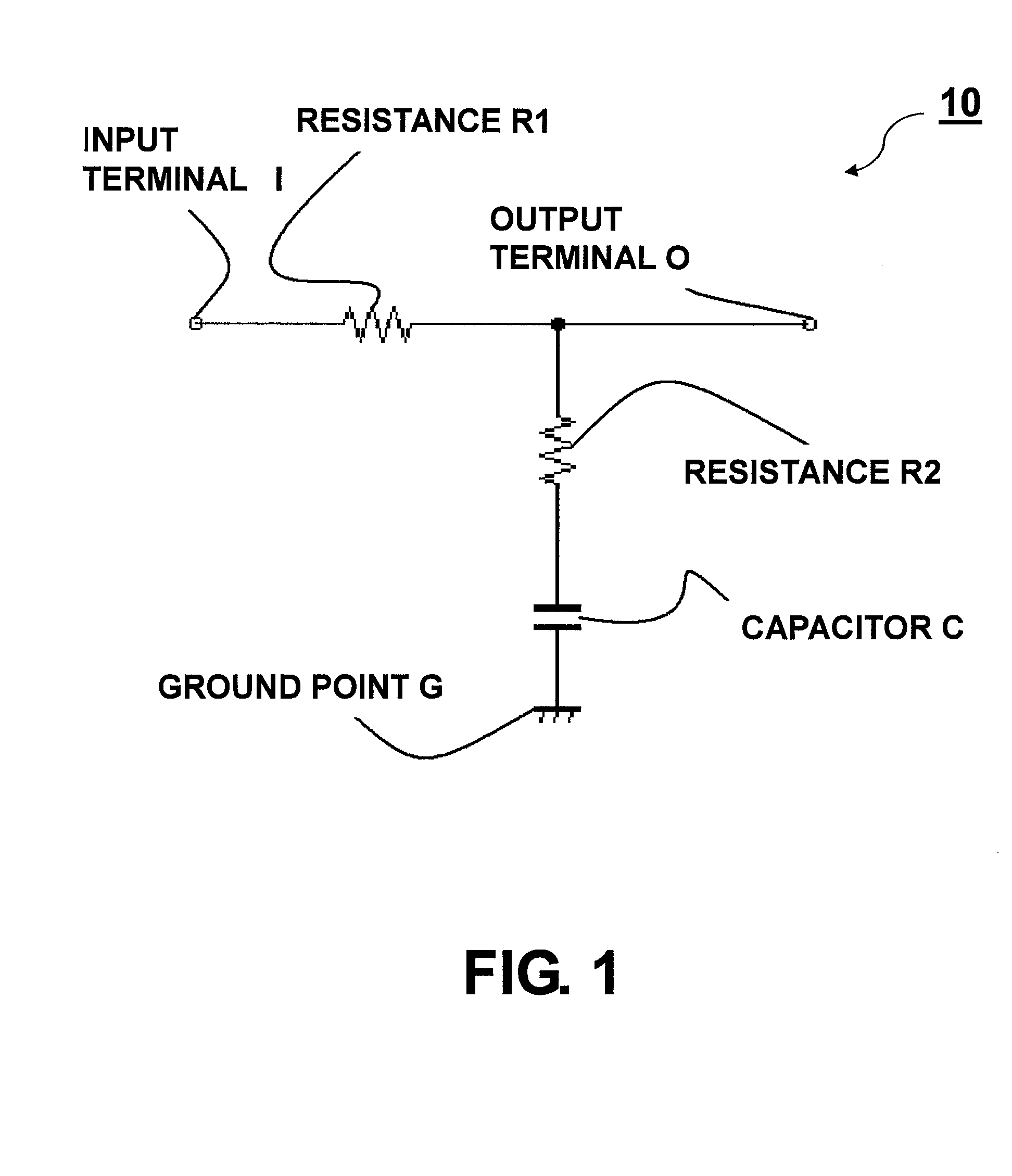
[0047]In FIG. 1, this low-pass filter circuit 10 is formed by: connecting a resistance R1, a resistance R2, and a capacitor C in series in this order between an input terminal I and a ground point G; and providing an output terminal O that picks up an output signal at a connection point of the resistance R1 (first resistance) and the resistance R2 (second resistance). A cutoff frequency fclp of the low-pass filter circuit 10 is determined according to a time constant obtained from: a combined resistance value R of the resistance R1 and the resistance R2, i.e., R1+R2; and a capacitance value of the capacitor C.

[0048]An output level of the low-pass filter circuit 10 can be obtained through the following formula:

√((1+(2πfCR2)2)) / (1+(2πfC(R1+R2))2)

[0049]Here, “f” denotes a frequency of an input signal. As with the conventional low-pass filter circuit, the low-pass filter circuit 10 attenuates frequencies higher than the cutoff frequency fclp. Moreover, when the frequency of the input si...

second embodiment

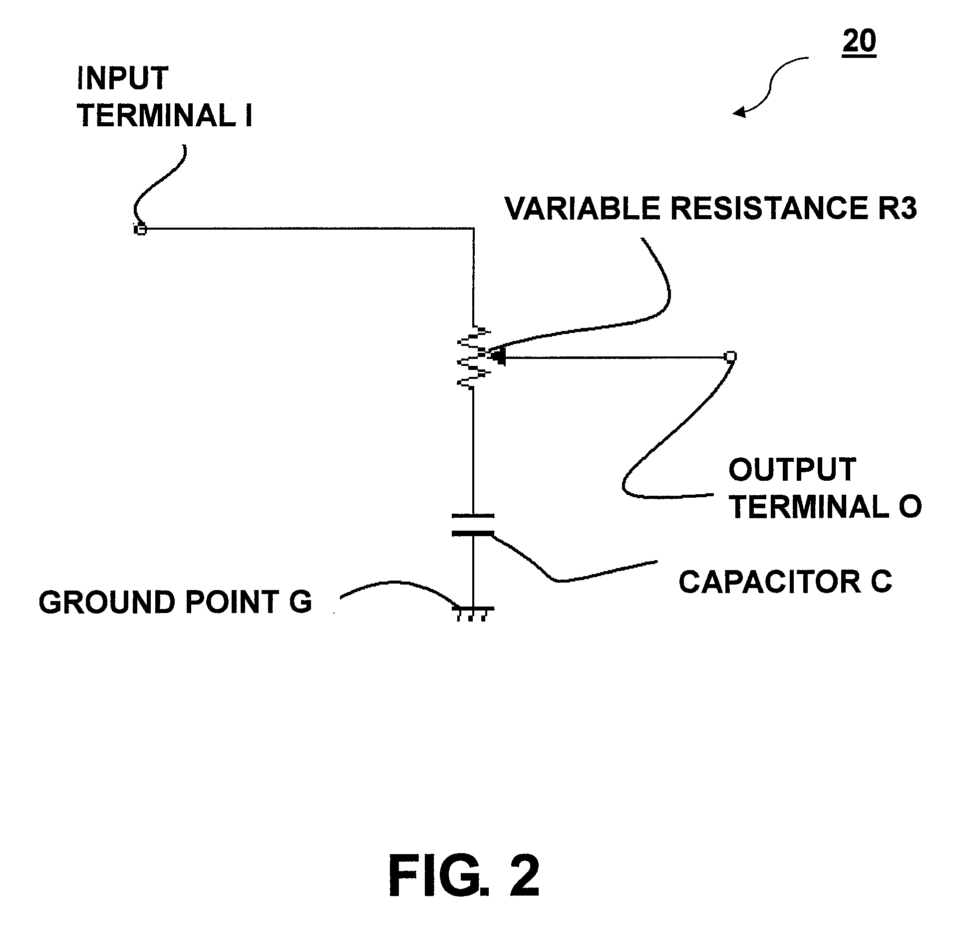
[0052]Another embodiment of the filter circuit of the present invention is shown in FIG. 2. A low-pass filter circuit 20 shown in FIG. 2 has, in place of the resistances R1 and R2 provided in the low-pass filter circuit 10, a variable resistance R3. In the low-pass filter circuit 20, the output terminal O is provided at a movable terminal of the variable resistance R3.

[0053]Thus, ratio of a resistance dividing the voltage of the input signal is variable by changing the position of the movable terminal. As a result, the low-pass filter 20 can provide the same effect as provided by the low-pass filter 10 by setting the resistance values of the resistances R1 and R2 with the certain resistance ratio Nr as in the first embodiment. Therefore, the filter circuit having the optimal phase characteristic can easily be obtained.

[0054]The maximum phase delay frequency will be explained. In the filter circuit of the present invention, as the frequency of the input signal becomes higher, the pha...

third embodiment

[0057]Still another embodiment of the filter circuit according to the present invention will be described. FIG. 4 is a circuit diagram depicting an example of a high-pass filter circuit as an example of the filter circuit according to the present invention. As shown in FIG. 4, this high-pass filter circuit 30 is formed by: connecting a capacitor C1, a capacitor C2, and a resistance R in series in this order between the input terminal I and the ground point G; and providing the output terminal O that picks up the output signal at a connection point of the capacitor C1 and the capacitor C2. A cutoff frequency fchp of the high-pass filter circuit 30 is determined based on a time constant obtained from: a combined capacitance value of the capacitor C1 and the capacitor C2, i.e., C1+C2; and a resistance value of the resistance R.

[0058]Similar to the conventional high-pass filter circuit, the high-pass filter circuit 30 outputs a frequency component higher than the cutoff frequency fchp, ...


PUM


Abstract

A filter circuit includes: an input terminal; a first resistance; a second resistance; a capacitor; and an output terminal, in which the first resistance, the second resistance, and the capacitor are connected in series in this order between the input terminal and a ground point, the output terminal is provided at a connection point of the first resistance and the second resistance, and a frequency domain is used that is higher than a maximum phase delay frequency higher than a cutoff frequency, the cutoff frequency being determined by a combined resistance value of the first and the second resistances and a capacitance value of the capacitor, so that when a frequency of an input signal becomes higher, a phase delay of an output signal relative to the input signal is reduced.

Description

BACKGROUND OF THE INVENTION[0001]1. Field of the Invention[0002]The present invention relates to a filter circuit, and more specifically to a filter circuit using a frequency domain with which, as a frequency of an input signal becomes higher, a phase advance of an output signal relative to the input signal increases, and as the frequency of the input signal becomes lower, a phase difference between the input and the output signals reduces.[0003]2. Description of the Related Art[0004]Various filter circuits for processing audio signals are known. Such filter circuits are represented by a filter circuit using an analog circuit. Examples of the filter circuit using the analog circuit include: a low-pass filter circuit that passes only frequencies lower than a cutoff frequency; a high-pass filter circuit that passes only frequencies higher than the cutoff frequency; a band-pass filter circuit that passes only frequencies included in a frequency band defined by two cutoff frequencies; a...

Claims


Application Information

Patent Timeline
Patent Type & Authority Applications(United States)
IPC IPC(8): H03G5/00
CPCH03H11/04H03H7/01
Inventor KIMURA, TOMINORI
Owner AUDIO-TECHNICA
Why Eureka
Try Eureka