Free-Space Optical Transceiver Using Multimode Fiber to Couple Single Mode Input Optical Signal

Active Publication Date: 2010-07-08
EOS DEFENSE SYST USA INC
View PDF8 Cites 11 Cited by
  • Summary
  • Abstract
  • Description
  • Claims
  • Application Information

AI Technical Summary

Benefits of technology

[0011]The present invention overcomes the limitations of the prior art by providing an optical circulator coupling optical fibers of dissimilar modes. In one embodiment, an optical circulator couples a single mode first fiber to a multimode second fiber, which is used as an optical input to a telescope. The multimode fiber does not

Problems solved by technology

For example, while the use of fiber optics has increased the capacity and efficiency of data transmission, expanding data transmission needs require continual additions to the fiber optics infrastructure at significant expense and difficulty.
However, this approach usually is not suitable for free space optical communications systems.
However, due to effects such as aberrations along the free space optical communications link and overfilling of the receive aperture, the light received by a transceiver typically does not have such a tightly controlled mode and cannot be efficiently coupled back into a single mode fiber.

Method used


Image

  • Free-Space Optical Transceiver Using Multimode Fiber to Couple Single Mode Input Optical Signal
  • Free-Space Optical Transceiver Using Multimode Fiber to Couple Single Mode Input Optical Signal
  • Free-Space Optical Transceiver Using Multimode Fiber to Couple Single Mode Input Optical Signal

Examples


Embodiment Construction

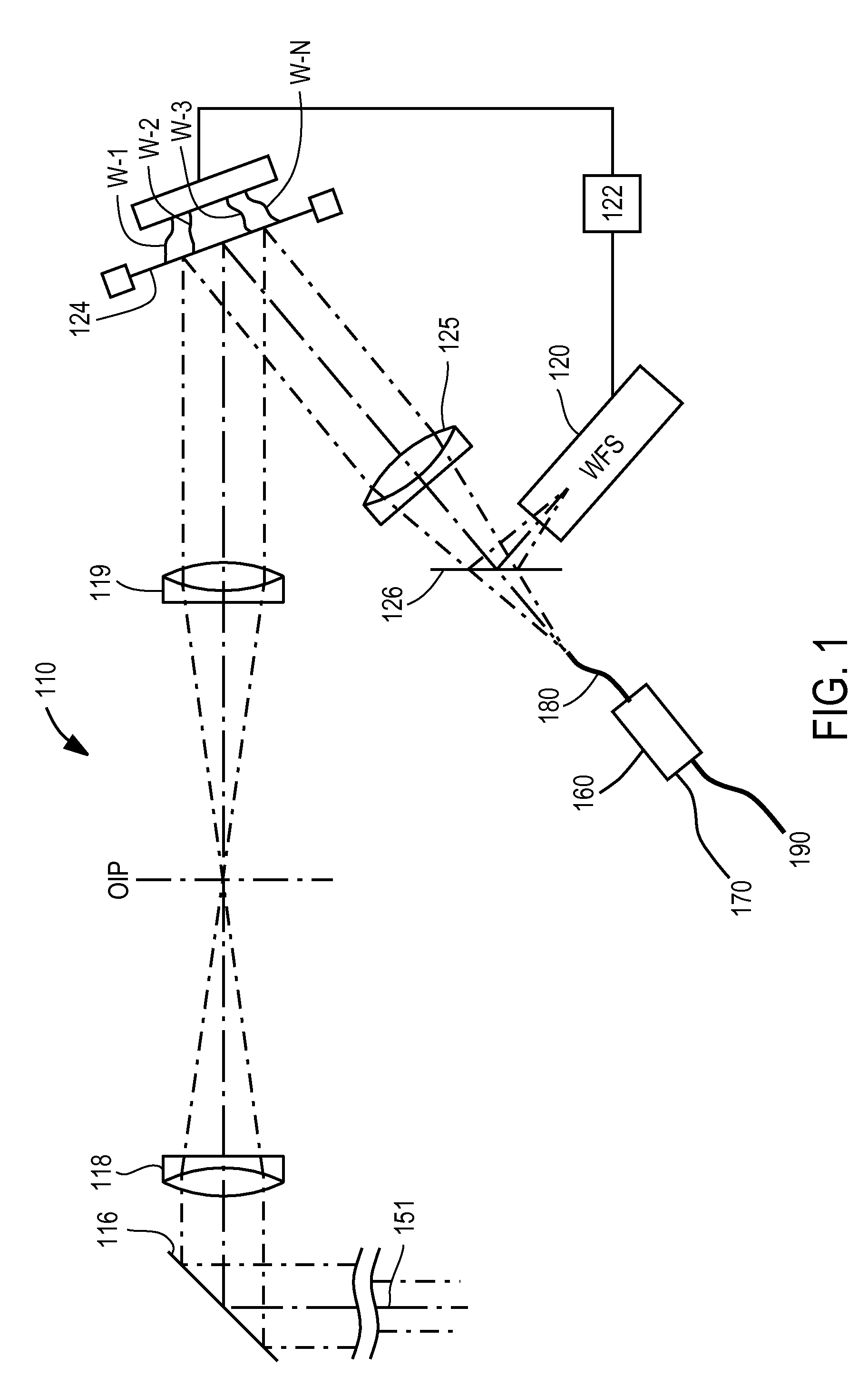
[0018]FIG. 1 is an illustration of an example optical train for a transceiver according to the invention. The system includes a telescope 110, a deformable mirror 124 and a wavefront sensor 120. The deformable mirror 124 and wavefront sensor 120 are located in the optical path of the telescope, with the wavefront sensor 120 downstream of the deformable mirror 124. The system also includes an optical circulator 160, with three ports. A single mode fiber 170 is coupled to port 1, a multimode fiber 180 to port 2 and a multimode fiber 190 to port 3. The other end of multimode fiber 180 functions as the optical input (or output) of telescope 110.

[0019]In the receive direction, the system collects light 151 from a remote source (e.g., from a transmitting telescope) and couples it into multimode fiber 180. The light then exits the circulator 160 via port 3 and multimode fiber 190. Multimode fibers 180 and 190 allow the capture of more light since the incoming optical beam may not be perfec...


PUM


Abstract

An optical circulator couples optical fibers of dissimilar modes. In one embodiment, an optical circulator couples a single mode first fiber to a multimode second fiber, which is used as an optical input to a telescope. The multimode fiber does not significantly degrade the mode structure of the light form the single mode fiber. In the reverse direction, light received by the telescope is coupled into the multimode second fiber, which the circulator couples to a multimode third fiber.

Description

CROSS-REFERENCE TO RELATED APPLICATION(S)[0001]This application claims priority under 35 U.S.C. §119(e) to U.S. Provisional Patent Application Ser. No. 61 / 143,137, “Free-Space Optical Transceiver Using Multimode Fiber to Couple Single Mode Input Optical Signal,” filed Jan. 7, 2009 by J. Elon Graves. The subject matter of the foregoing is incorporated herein by reference in its entirety.BACKGROUND OF THE INVENTION[0002]1. Field of the Invention[0003]This invention relates to optical transceivers used in free space optical communications systems.[0004]2. Description of the Related Art[0005]There is a rapidly expanding need for data transmission. For example, while the use of fiber optics has increased the capacity and efficiency of data transmission, expanding data transmission needs require continual additions to the fiber optics infrastructure at significant expense and difficulty. One approach to augmenting the data transmission system is through the use of free space optical commu...

Claims


Application Information

Patent Timeline
IPC IPC(8): H04B10/10
CPCH04B10/1123
Inventor GRAVES, J. ELON
Owner EOS DEFENSE SYST USA INC
Why Eureka
Try Eureka