Method of manufacture of low water peak single mode optical fiber

Inactive Publication Date: 2005-01-06
YANGTZE OPTICAL FIBRE & CABLE CO LTD
View PDF11 Cites 64 Cited by
  • Summary
  • Abstract
  • Description
  • Claims
  • Application Information

AI Technical Summary

Benefits of technology

The advantages of the present invention are as follows.
1. The attenuation of the optical fiber manufactured by the method provided by the present invention is less than 0.344 dB/km at 1310 nm, less than 0.334 dB/km at 1383 nm, less than 0.224 dB/km at 1550 nm. The attenuation at 1383 nm is lower than the stipulated value at 1310 nm. According to the method of hydrogen loss measurement provided by IEC, the optical fiber is placed in an atmosphere with its H2 partial pressure being 0.01 atm at room temperature, and the attenuation increase of the optical fiber at 1240 nm is continuously monitored. When the attenuation increases beyond 0.03 dB/km at 1240 nm, the optical fiber is rem

Problems solved by technology
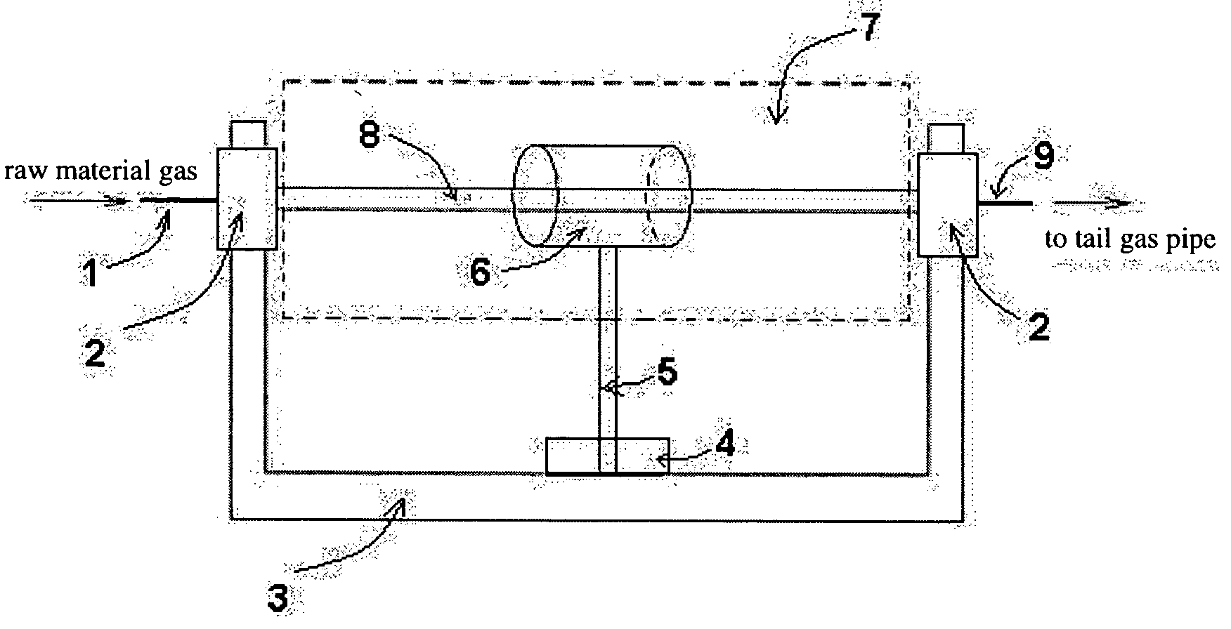
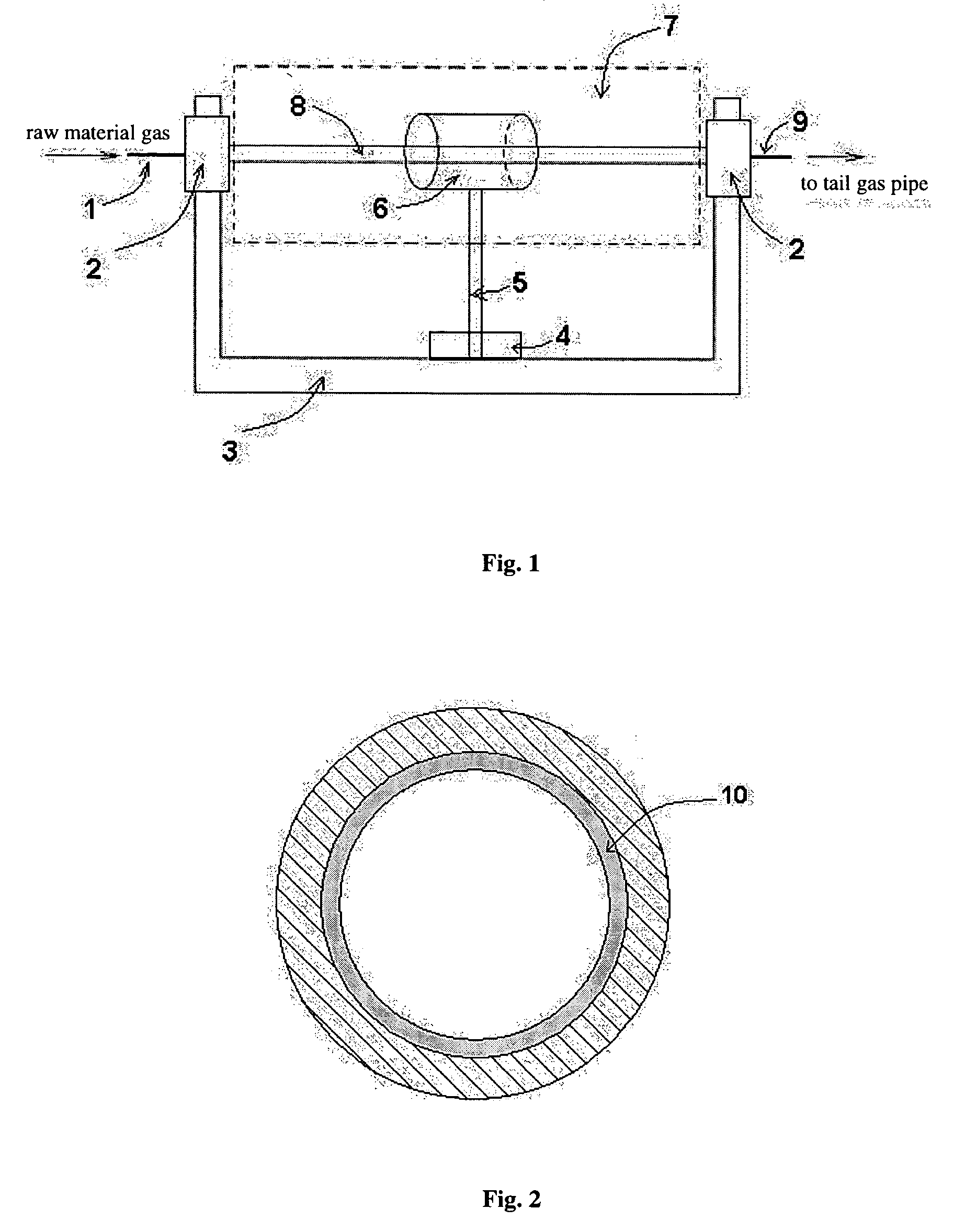
However, it is difficult to remove hydroxyl groups in the preform by the described method.
Patent Application 98813827.1 describes an improved PCVD apparatus and method for preparation of preforms, but it does not solve the problem of high attenuation caused by the water peaks of fiber yet.
This method, howev

Method used


Image

  • Method of manufacture of low water peak single mode optical fiber
  • Method of manufacture of low water peak single mode optical fiber
  • Method of manufacture of low water peak single mode optical fiber

Examples


example 1

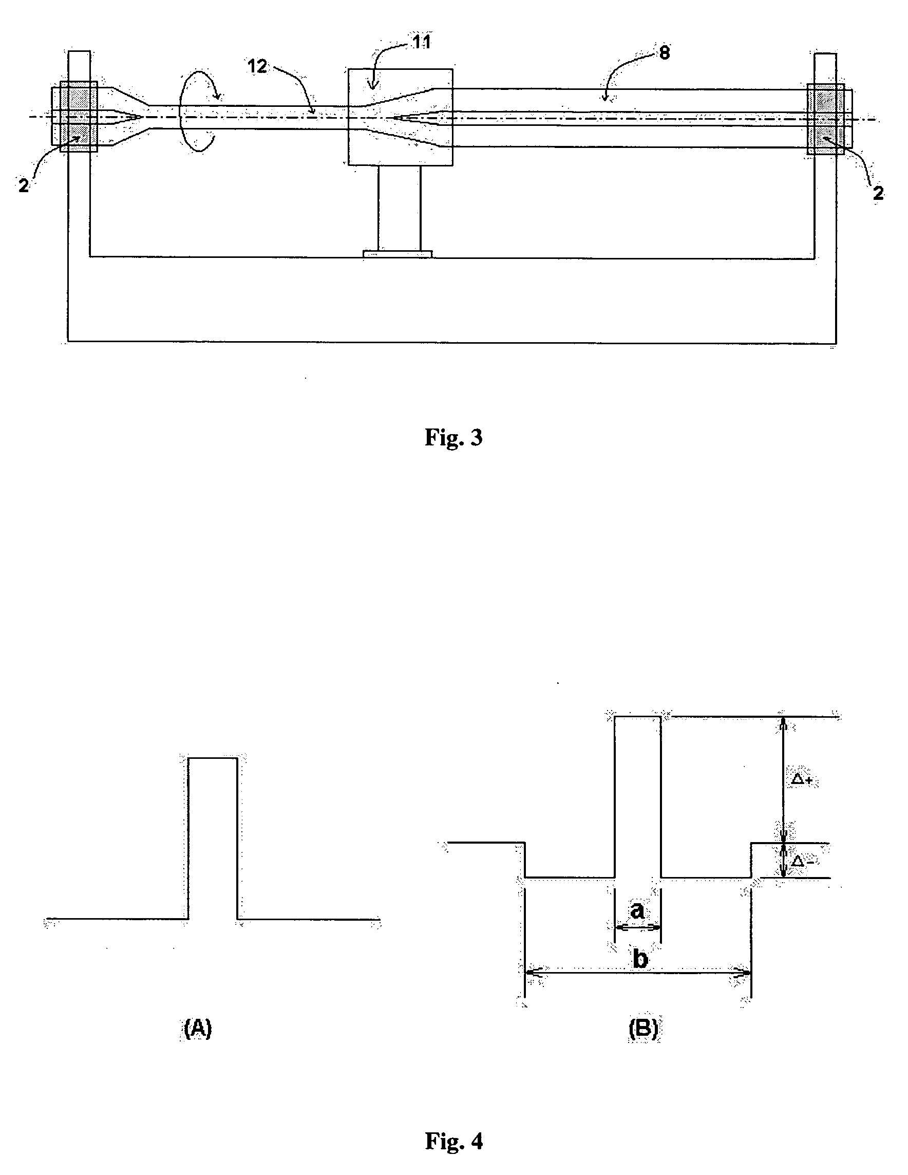
In an “non-water” environment of dry air (relative humidity, 0%, temperature, 25° C.), highly pure raw materials SiCl4, GeCl4, C2F6 and O2 (wherein the infrared transmissivity of impurities SiCl3OH and GeCl3OH are 99.9%, water content of C2F6 is 8 ppb, water content of O2 is 0.9 ppb), are introduced into a substrate tube of hydroxyl content of 9 ppb, and deposition is carried out by PCVD described above in a deposition machine with the dynamic leak rate of 1.0×10⁻⁹ mbar·l / s. The controlled b / a value is 4.0, the refractivity contribution of freon doped in a cladding is −0.15%, the value of Δ− of the cladding doped with freon and germanium is −0.02%, the refractivity contribution of freon doped in a core layer is −0.07%, the value of Δ+ of the core layer doped with freon and germanium is 0.33%.

In the environment of the same humidity and temperature, the substrate tube is melt contracted with a graphite electroheating furnace in a melt contraction machine whose dynamic leak rate is ...

example 2

Using a procedure similar to that in Example 1, in this case, in an “non-water” environment of dry air (relative humidity, 5%, temperature, 23° C.), highly pure raw materials SiCl4, GeCl4, C2F6 and O2 (wherein the infrared transmissivity of impurity SiCl2OH is 96% and that of impurity GeCl3OH is 98%, water content of C2F6 is 50 ppb, water content of O2 is 8 ppb) are introduced into a substrate tube of hydroxyl content of 85 ppb for deposition. During deposition a mixed gas containing deuterium (1% D2+99% He) is introduced. Under the condition that the dynamic leak rate of the deposition machine is 1.0×10⁻⁷ mbar·l / s, control the deposition process performs under the conditions of b / a value equals 7.0. The refractivity contribution of freon doped in the cladding is −0.20%, the value of Δ− of the cladding doped with freon and germanium is −0.03%, the refractivity contribution of freon doped in the core layer is −0.20%, the value of Δ+ of the core layer doped with freon and germanium i...

example 3

A procedure similar to that of the previous two examples is used. In the raw materials SiCl4, GeCl4, C2F6 and O2, the infrared transmissivity of impurity SiCl3OH is 92%, that of GeCl3OH is 94%, water content of C2F6 is 200 ppb, water content of O2 is 75 ppb. Hydroxyl content of the substrate tube is 600 ppb. Hydroxyl content of the jacket tube is 5 ppm. Deposition is performed by the above described PCVD technology, whose b / a value is 2.0. The refractivity contribution of freon doped in the cladding is −0.05%, the value of Δ− of the cladding doped with freon and germanium is 0.01%, the refractivity contribution of freon doped in the core layer is −0.05%, the value of Δ+ of the core layer doped with freon and germanium is 0.40%.

The dynamic leak rate of the deposition machine used is 1.0×10⁻⁵ mbar−l / s. The dynamic leak rate of melt contraction machine used is 1.0×10⁻⁵ mbar·l / s. The environment provided by dry air has a relative humidity of 25% and a temperature of 25° C.

The diame...


PUM

PropertyMeasurementUnit
Temperatureaaaaaaaaaa

Abstract

The present invention directs to a method of manufacturing low water peak single mode optical fiber, which comprises performing deposition in a substrate tube using PCVD technology, whereby a deposited layer of a certain construction design is formed on the inner wall of the substrate tube, melt contracting the substrate tube into a solid core rod according to melt contraction technology, producing an optical fiber preform by combining the core rod and a jacket tube of low hydroxyl content by means of RIT technology or by depositing an outer cladding on the outer surface of the core rod using OVD technology, sending the optical fiber preform into a fiber drawing furnace to draw it into an optical fiber, wherein: in the PCVD technology, the content of impurities in a gas mixture of raw materials, which is characterized by the infrared spectrum transmissivity thereof, is required to a transmissivity of 90% or greater, the water content in O2 is 100 ppb or less, the water content in C2F6 is 1000 ppb or less, the hydroxyl content of the substrate tube is 1000 ppb or less, the dynamic leak rate of a deposition machine is 1.0×10⁻⁵ mbar·l/s or less; during melt contraction of the substrate tube, the dynamic leak rate of a melt contraction machine is 1.0×10⁻⁵ mbar·l/s or less; the hydroxyl content of the jacket tube of low hydroxyl content is required to be 10 ppm or less; the relative humidity of environment during the process of manufacture is 25% or less; the ratio of the cladding diameter to the core layer diameter (b/a value) in the waveguide structure of the optical fiber is from 2.0 to 7.0.

Description

CROSS-REFERENCE TO RELATED APPLICATION(S) The present application claims priority to Chinese Patent Application No. 03128228.8, filed on Jun. 27, 2003, the contents of which is incorporated by reference herein in its entirety. TECHNICAL FIELD The present invention relates to a method of reducing the hydroxyl content of optical fiber preform for the manufacture of low water peak single mode fiber, in particular, a method of manufacture of low water peak single mode optical fiber at low cost in which an optical fiber preform is produced by means of plasma chemical vapor deposition with adjusting process parameters and controlling raw material and environmental factors. TECHNICAL BACKGROUND With the rapid growth of traffic of communication information, the size of optical network of wavelength division multiplexing (WDM) technique and transmission capacity are continuously increasing. WDM systems are capable of simultaneously transmitting optical carrier waves of various wavelengths...

Claims


Application Information

Patent Timeline
IPC IPC(8): C03B37/018
CPCC03B37/01807C03B37/0183C03B37/01853C03B37/01861C03B37/01892C03B2207/32C03B2201/075C03B2201/12C03B2201/22C03B2201/31C03B2207/30C03B2201/04
Inventor XIE, KANGZHANG, SHUQIANGHAN, QINGRONGWANG, TIEJUNTU, CHENGHOUMATAI, RAJI
Owner YANGTZE OPTICAL FIBRE & CABLE CO LTD
Why Eureka
Try Eureka