Controller for fuel cell operation

a fuel cell and control device technology, applied in the field of fuel cell control, can solve the problems of high cost, high power consumption, and active valves

Inactive Publication Date: 2010-07-08
ARDICA TECH
View PDF99 Cites 20 Cited by
  • Summary
  • Abstract
  • Description
  • Claims
  • Application Information

AI Technical Summary

Benefits of technology

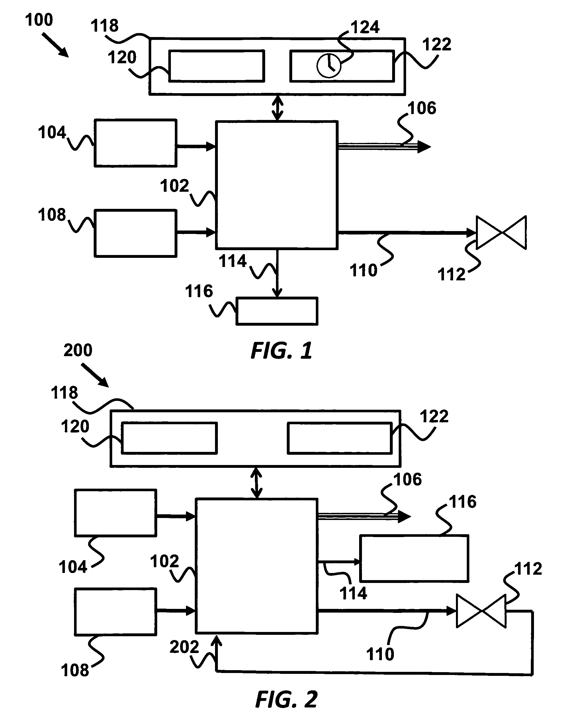
[0006]The current invention is a fuel cell controller that includes a first control loop, where the first control loop is disposed to adjust a fuel cell current to regulate a hydrogen output pressure from the fuel cell to a pressure target value, and further includes a second control loop disposed to adjust a hydrogen flow rate from a hydrogen generator to match a fuel cell power output to a power target value.

Problems solved by technology

Additionally, fuel cell systems often employ safety valves that allow gas to escape if the internal pressure or vacuum builds to unsafe levels, preventing damage to the device and / or hazards to users.
These active valves suffer from a number of problems including high cost and high power consumption.
Additionally, they are unreliable as a safety purge valve, as they require proper external control in order to function properly.
The response time of such systems is often characterized by latency and long time constants that are due to finite thermal mass and mass transfer limitations of the chemical hydrogen reactor systems.
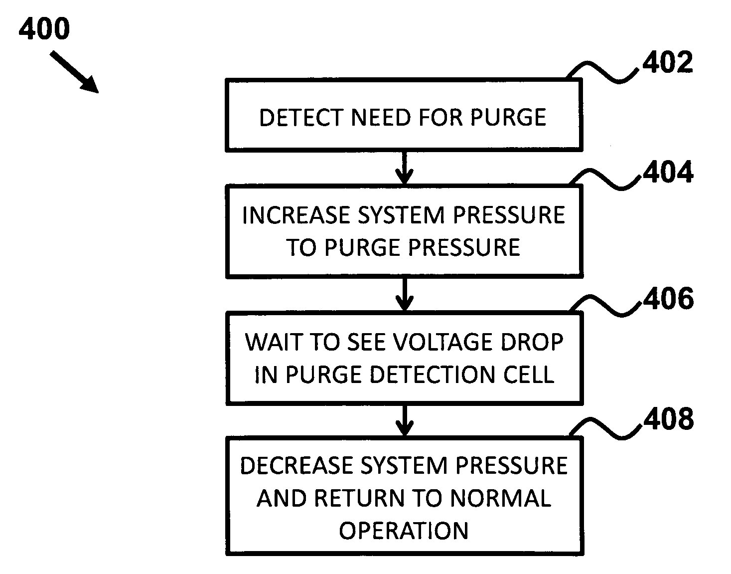
These limitations make frequent rapid pressure changes impossible and thus purging based on passive purge valves impractical.
Additionally, the current fuel cell systems often operate with hydrogen stored at elevated pressures, requiring high pressure rated gas routing, as well as down pressure regulators, that add system weight.
Furthermore, high pressure hydrogen gas routing poses safety challenges in fault modes.

Method used


Image

  • Controller for fuel cell operation
  • Controller for fuel cell operation
  • Controller for fuel cell operation

Examples


embodiment 500

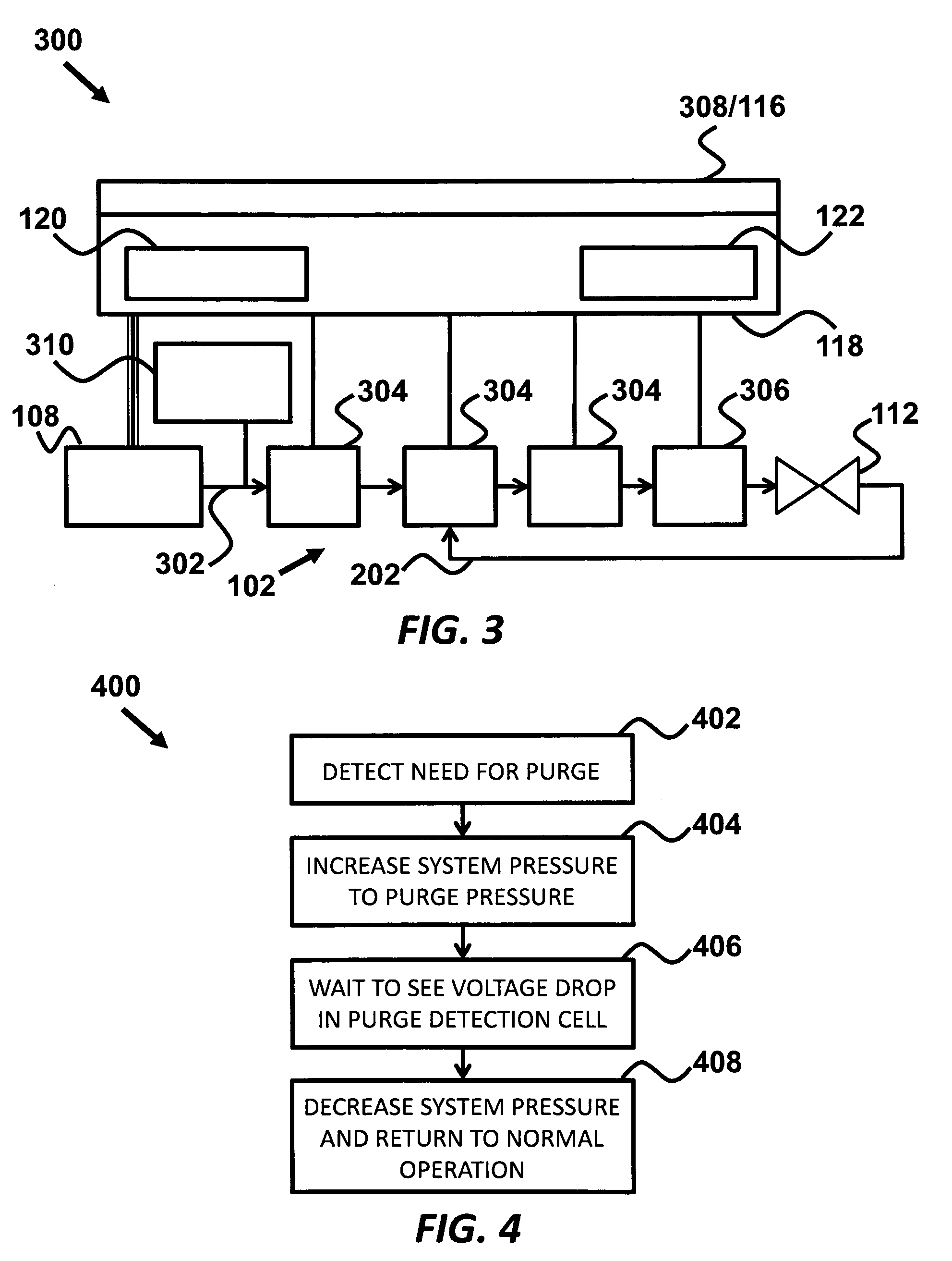
[0033]FIG. 5 shows an auxiliary fuel cell embodiment 500 that includes a purge exhaust 202 routed to an anode of an auxiliary fuel cell 502, while the cathode of the auxiliary fuel cell 502 is supplied with oxygen by air, either from an active air-move 506 such as a fan or preferably passively by diffusion. The purge exhaust 202 from the passive purge valve 112 is directed to a hydrogen sensor such as an anode of an auxiliary fuel cell 502, where the purge complete module 122 determines when the non-fuel matter 110 has been purged by sensing when the output 504 of the auxiliary fuel cell 502 exceeds a threshold level, where the output 504 can be either voltage or current. Initially when inert gas and other non-fuel matter 110 such as water vapor / condensation, is being purged into the anode the open cell voltage of the auxiliary fuel cell 502 is low and cell current when loaded is minimal. Once all of the inert gas 110 has been purged and instead pure hydrogen is being purged the ope...

embodiment 600

[0034]According to another embodiment FIG. 6 shows a catalyst bed embodiment 600 that includes a purge exhaust 202 routed to a catalyst bed 602 in the presence of ambient air 604. Here the purge complete module 122 determines when the non-fuel matter 110 has been purged by sensing when the temperature 606 of the catalyst bed 602 exceeds a threshold level. The structure of the catalyst bed allows mixing of the purge exhaust 202 with ambient air 604 e.g. by diffusion, or venturi entraining. Initially, when inert gas and other non-fuel matter 110 such as water vapor / condensation, is being purged into the catalyst bed the gases pass through the catalyst bed without any reaction. Once all of the inert gas 110 has been purged and instead pure hydrogen is being purged, the hydrogen mixed with oxygen from ambient air catalytically combust at the catalyst bed, releasing heat and water vapor. The measured temperature increase 606 of the catalyst bed 602 is a good indication of hydrogen purity...


PUM

PropertyMeasurementUnit
pressureaaaaaaaaaa
hydrogen flow rateaaaaaaaaaa
currentaaaaaaaaaa

Abstract

The current invention is a fuel cell controller that includes a first control loop, where the first control loop is disposed to adjust a fuel cell current to regulate a hydrogen output pressure from the fuel cell to a pressure target valve, and further includes a second control loop disposed to adjust a hydrogen flow rate from a hydrogen generator to match a DC/DC power output to a power target value.

Description

CROSS-REFERENCE TO RELATED APPLICATIONS[0001]This application is a Continuation in Part of claims priority to application and Ser. No. 12 / 322,337 filed Jan. 29, 2009, which is cross-referenced to and claims the benefit from U.S. Provisional Application 61 / 062,961 filed Jan. 29, 2008, and which are hereby incorporated by reference.FIELD OF THE INVENTION[0002]The invention relates generally fuel cells. More particularly, the invention relates to a system for controlling fuel cell in conjunction with an on demand hydrogen generator.BACKGROUND[0003]Fuel cell systems where oxygen is supplied from ambient air accumulate the non-reactive components of air (primarily nitrogen and some water vapor or condensation) in the fuel stream due to finite diffusion rates of gases through the fuel cell electrolyte. The inert gas accumulation eventually lowers the fuel cell output voltage due to drop of fuel concentration. As a consequence, continuous operation requires periodic purging of the fuel com...

Claims


Application Information

Patent Timeline
Patent Type & Authority Applications(United States)
IPC IPC(8): H01M8/04
CPCH01M8/0273Y02E60/50H01M8/04089H01M8/04231H01M8/04402H01M8/04552H01M8/04753H01M8/04761H01M8/04776H01M8/0491H01M8/0606H01M8/1097H01M8/2475H01M16/006H01M2250/30Y02B90/18H01M8/04067Y02B90/10Y02E60/10H01M8/0438H01M8/04544H01M8/04574H01M8/04895H01M8/04902H01M8/04925H01M8/04932H01M8/0494H02J7/00
Inventor FABIAN, TIBORFISHER, TOBIN J.BRAITHWAITE, DANIEL
Owner ARDICA TECH
Why Eureka
Try Eureka