Junction Box in Connecting Box for a Solar Module

a solar module and junction box technology, applied in the direction of coupling contact members, coupling device connections, coupling/disassembly of coupling parts, etc., can solve the problems of reducing the power of solar modules in series connection, affecting the reliability of contact, and affecting the service life of solar modules, etc., to achieve the effect of long service life and high contact reliability

Inactive Publication Date: 2010-07-08
PHOENIX CONTACT GMBH & CO KG
View PDF5 Cites 19 Cited by
  • Summary
  • Abstract
  • Description
  • Claims
  • Application Information

AI Technical Summary

Benefits of technology

[0010]Therefore, it is an object of the present invention to provide a connection and junction box for a photovoltaic solar module, which box can automatedly, for example by means of a robot, be connected to the solar module, and offers high contact reliability and long-life cycle.
[0012]It is a further object of the invention to provide such a connection and junction box, which avoids, or at least lowers the disadvantages of the state of the art, and may cost-effectively be produced as well as be mounted.
[0015]The connection and junction box according to the invention may easily be mounted, particularly by means of a robot arm. It is advantageous that the flexible flat conductor band is inserted in a resistance-less, and even contactless manner, if needed, into the insertion mouth besides the contact clamp, and therewith outside the contact or insertion area so that damaging the sensitive flat conductor band is avoided. Particularly, the insertion mouth may be chosen relatively large so that there is a kind of tolerance concerning the lateral arrangement of the connection and junction box on the solar module, and that it is avoided that the conductor band abuts against parts of the connection and junction box.
[0016]Furthermore, due to bending the flat conductor band may course diagonally or even parallelly to the surface of the solar module at the clamp position so that the clamping force of the contact clamp may act diagonally or even perpendicularly to the surface of the solar module. Furthermore, bending causes some movability of the flat conductor band, what may contribute to long-life cycle.
[0021]This has the advantage that in case of an automated mounting of the connection and junction box on the solar module, only one work step with a linear movement has to be carried out. This is particularly easy for a mounting robot.
[0023]Preferably, the contact clamp has a clamp spring and a counter clamp element, of which at least one of the two has electric contact section, and wherein the electric contact with the float conductor band is closed by means of an active movement of the clamp spring or the counter clamp element, in response to actuation by means of the second actuation element. For this, it may easily be implemented to pivotably mount the clamp spring at the connection device, and to close the electric contact with the flat conductor band by means of pivoting the clamp spring, in response to the actuation by means of the second actuation element. At this, a clamp section of the clamp spring covers the catch area between the clamp spring and the counter clamp element for catching the bent flat conductor band. Thereby, the catch area is preferably relatively large during bending. It is free of resistance and barriers so that the danger of damaging the flat conductor band is avoided during bending.

Problems solved by technology

These flexible conductor bands are very sensitive and therefore difficult to contact.
Additionally, a mechanical charge for fixing an electrical connector is also difficult because of the disk-like form of the solar module.
If a module is shaded or does not produce electricity because of a defect, this module would lower the power of the solar modules in series connection or even suffers damage without bypass diode.
It is apparent that due to the mechanical conditions, particularly the form of the solar module and the sensitiveness of the flexible flat conductor bands, a number of difficulties occur, when constructing the connection and junction box.
It is apparent that mounting such connection devices or connection boxes respectively is laborious, and is badly suited for automated mass production.
At this, it is disadvantageous that the conductor band has to be threaded into the narrow guiding arrangement, and the clamping force of the clamp arrangement may nevertheless be relatively low to be able to insert the thin conductor band into the clamp arrangement.

Method used


Image

  • Junction Box in Connecting Box for a Solar Module
  • Junction Box in Connecting Box for a Solar Module
  • Junction Box in Connecting Box for a Solar Module

Examples


Embodiment Construction

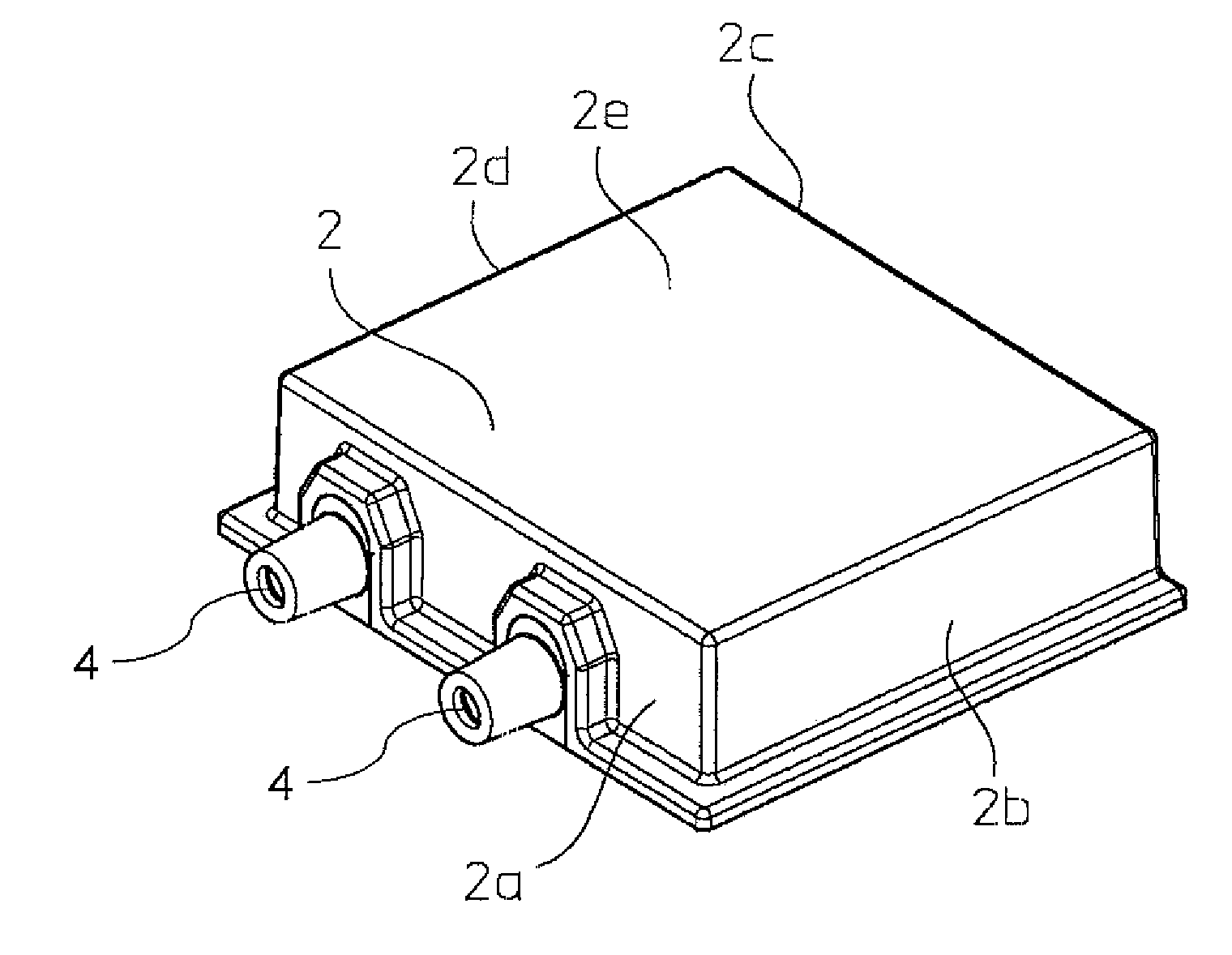
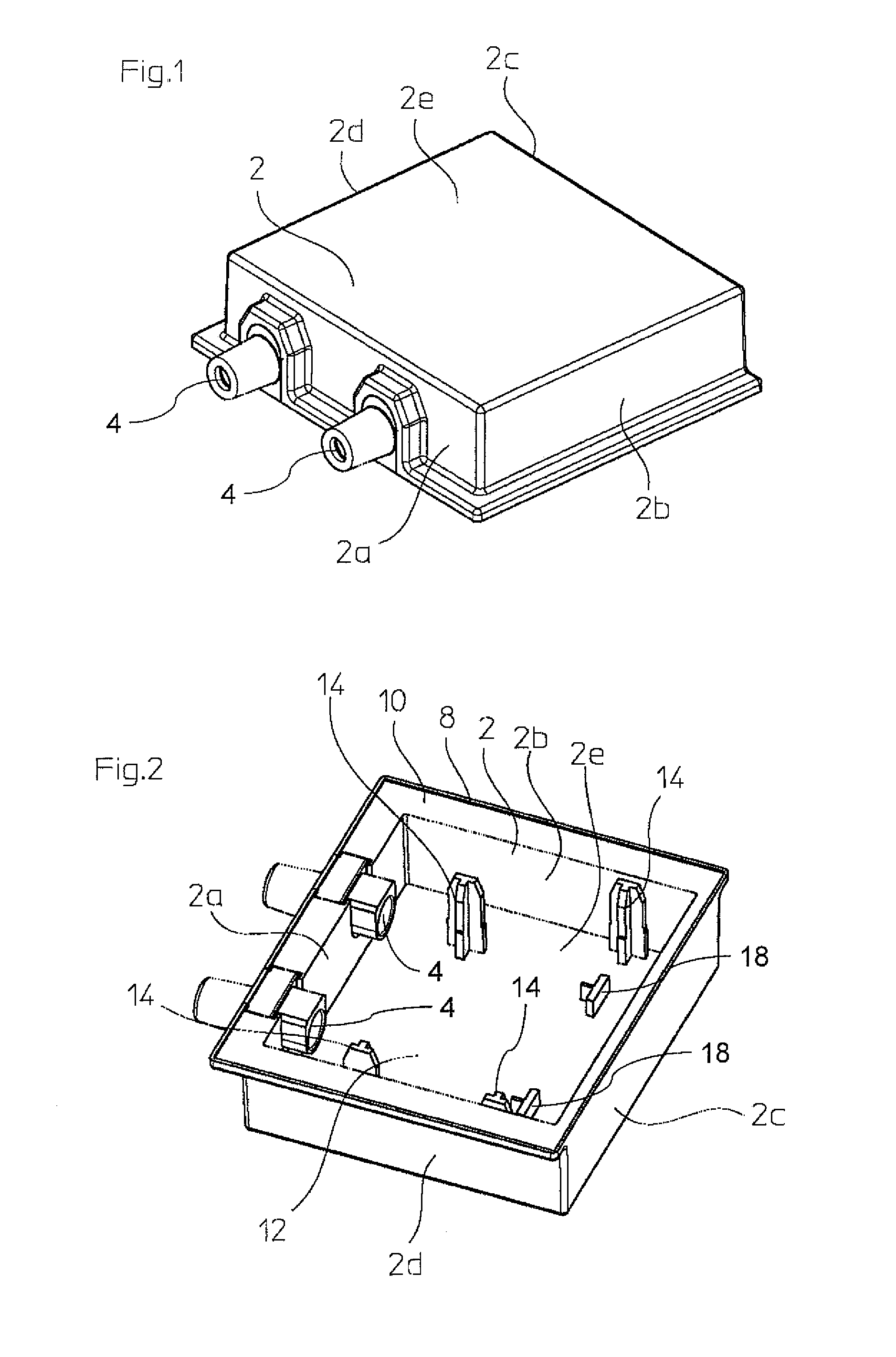
[0037]With reference to FIGS. 1 and 2, the connection and junction box has a housing made from plastic. The housing 2 is provided by an substantially rectangular frame consisting of four side walls 2a to 2d, and a closed cap 2e, which connects the four side walls and proceeds parallelly to the solar module. The five-sided, closed housing 2 being open downwards is die cast in one piece, for example. The connection cable (not shown) is guided outwards through connection cable feedthroughs 4.

[0038]With reference to FIG. 2, the housing 2 is open downwards, and has a protruding holding frame 8 with a circular glue notch 10 so that the housing 2 has a hat-like form. The housing is permanently glued on the solar module, and sealed by means of the glue brought into the glue notch 10. The hat-like or pan-like form of the housing defines an internal hollow space 12, in which the connection device not being shown in FIG. 2 is substantially waterproof housed in mounting state. The connection de...


PUM

PropertyMeasurementUnit
flexibleaaaaaaaaaa
forceaaaaaaaaaa
tensionaaaaaaaaaa

Abstract

A connection and junction box for a photovoltaic solar module having flexible flat conductor bands protruding from the surface of the solar module, wherein the connection and junction box has an insertion mouth at its side in mounting state facing the solar module, for at least one of the flexible flat conductor bands of the solar module, as well as comprising a housing for attaching to the solar module, and a connection device for the flexible flat conductor band, positioned in the housing, the connection device has a deflection arm and an electrical contact clamp, which is actuated when attaching the box to the solar module for bending and contacting the flat conductor band.

Description

FIELD OF THE INVENTION[0001]The invention relates to a connection and junction box for a photovoltaic solar module having flexible flat conductor bands protruding from the surface of the solar module, and to a method for connecting a connection and junction box to a solar module.BACKGROUND OF THE INVENTION[0002]Over the past years, producing photovoltaic solar modules has literally been booming, inter alia due to the increased demand on environmentally sound energy production. The direct conversion of sunlight into electric current by means of photovoltaic solar modules is entirely emission-free, and no risks for humans and the environment are almost involved. For example, complete roofs of new buildings are therefore recently overlaid with solar modules, and even “solar power plants” are built. Due to the technical development of photovoltaics, using solar modules more and more becomes efficient even in more unfavourable latitudes such as Middle Europe and Northern America so that ...

Claims


Application Information

Patent Timeline
Patent Type & Authority Applications(United States)
IPC IPC(8): H01R13/62H01R13/60H01R43/00
CPCH01R4/489Y10T29/49117H02S40/34H01R12/592H01L31/02013H01R9/2416Y02E10/50H01R4/4809H01R24/58H01R2103/00H02G3/083H02G3/16
Inventor GIEFERS, STEFAN
Owner PHOENIX CONTACT GMBH & CO KG
Why Eureka
Try Eureka