Device for driving a gas discharge lamp

a technology of gas discharge lamp and device, which is applied in the direction of lighting apparatus, electrical equipment, light sources, etc., can solve the problems of acoustic resonance, unpredictable behavior of arcs, and particularly serious problems, and achieve the effects of simple circuit implementation, accurate clock signal production, and simple components

Inactive Publication Date: 2010-07-15
KONINKLIJKE PHILIPS ELECTRONICS NV
View PDF7 Cites 1 Cited by
  • Summary
  • Abstract
  • Description
  • Claims
  • Application Information

AI Technical Summary

Benefits of technology

[0015]An important advantage of the implementation proposed by the present invention is that the clock device and the memory device are independent, “stand alone” devices which function independently from each other. The invention allows for the use of a voltage controlled oscillator, which results in a relatively simple circuit implementation, while further a VCO is specifically designed for accurately producing a clock signal and, in contrast to a processor, a VCO has no further task but to produce a clock signal. A further advantage is that the clock device and the memory device are relatively simple components: if the quasi-random bridge control signal would have to be generated by a processor, this would require much processor capacity and would hence necessitate the use of a large and expensive processor.

Problems solved by technology

An important problem of gas discharge lamps is the possibility of acoustic resonances, i.e. pressure resonances, occurring typically but not exclusively in the range from 9 kHz to 1 MHz, and this problem is particularly serious in the case of HID lamps.
As a result of acoustic resonances, the behavior of the arc becomes unpredictable, and possibly unstable; the arc can touch the vessel, damaging the vessel, and the arc can extinguish.
However, DC operation also involves some disadvantages, including asymmetric erosion of the electrodes and color-segregation.
Having a processor operate at the required high frequency makes such processor relatively expensive.
When current frequencies higher than 1 MHz are used, design problems occur in relation to circuit components, these problems typically relating to efficiency, size, and costs.
Thus, it would be very difficult to find a frequency setting where acoustic frequencies are guaranteed not to occur.
Further, having the modulation scheme performed by a processor would take up much capacity of such processor, and the required circuit would be relatively complicated.

Method used


Image

  • Device for driving a gas discharge lamp
  • Device for driving a gas discharge lamp
  • Device for driving a gas discharge lamp

Examples


Embodiment Construction

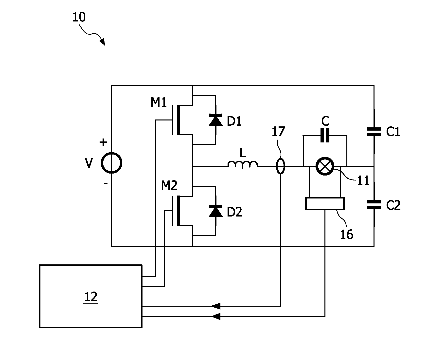
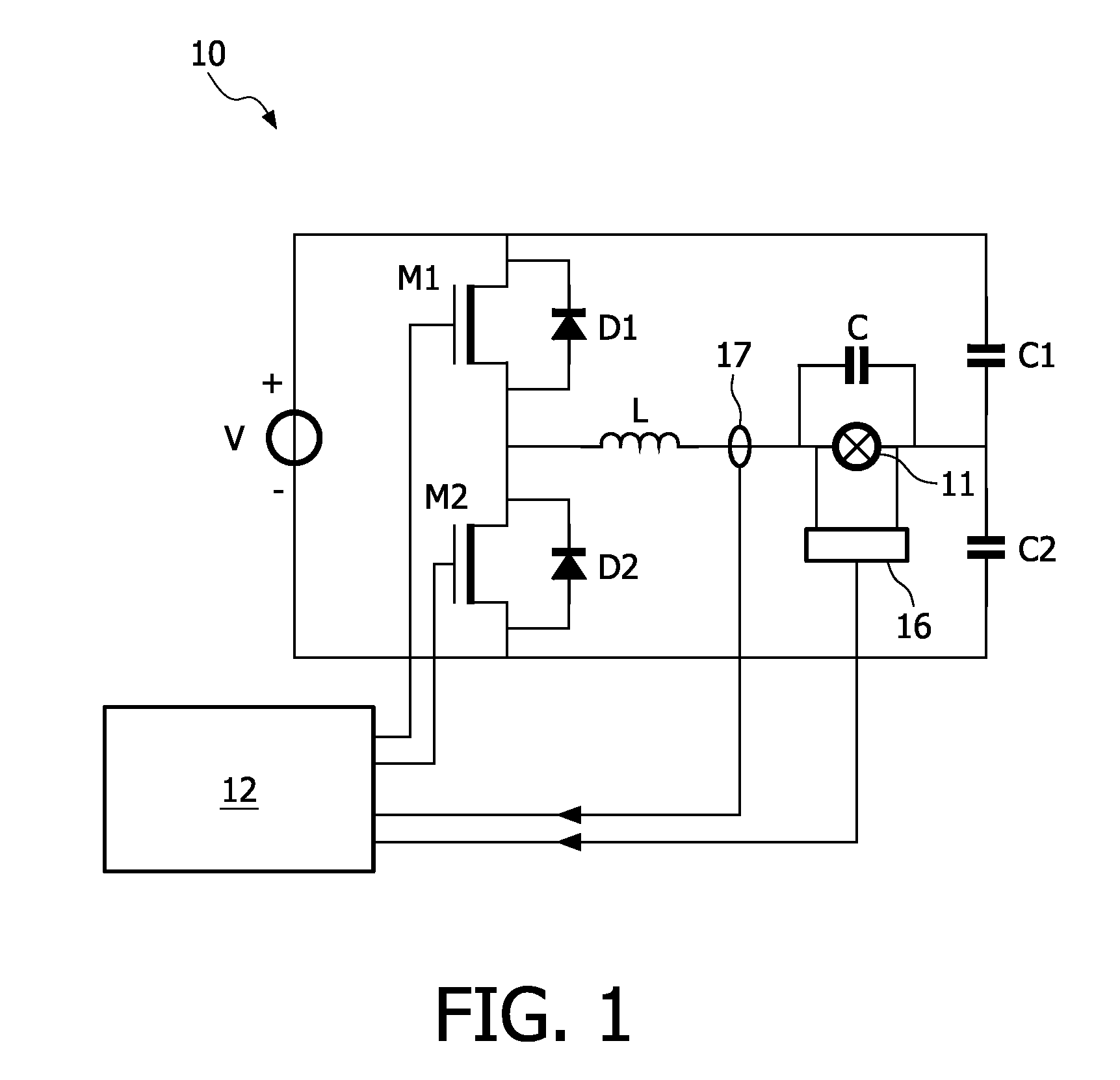
[0020]FIG. 1 is a block diagram schematically illustrating a lamp driver 10 with half-bridge topology, for driving a gas discharge lamp 11. Since such half-bridge circuit topology should be known to persons skilled in the art, the design and functioning will be described only briefly. Two switches M1 and M2 are arranged in series, with corresponding diodes D1, D2, between two voltage rails coupled to a source of substantially constant voltage V. The design of this voltage source is not relevant for the present invention. Two capacitors C1 and C2 are also arranged in series between the two voltage rails. The lamp 11 is coupled between on the one hand the junction between the two switches M1 and M2 and on the other hand the junction between the two capacitors C1 and C2, with an inductor L arranged in series with the lamp 11 and a capacitor C arranged in parallel with the lamp 11. The two switches M1 and M2 are controlled alternately by a controller 12, such that they are never closed ...


PUM


Abstract

A driver (10) for driving a gas discharge lamp (11) comprises at least two controllable switches (M1, M2) and a controller (12) for controlling the switches. The controller has a first operative state in which one switch (M1) is conductive while the other switch (M2) is non-conductive, and has a second operative state in which said other switch (M2) is conductive while said first switch (M1) is non-conductive. The controller comprises a memory device (20) comprising a plurality of memory elements (21) each containing a binary value (“0”; “1”), wherein the value of the last memory element (21(N)) determines the operative state of the controller. Responsive to a clock signal (SQL) generated by a clock device (30), the memory device shifts the contents of each memory element (21(i)) to a subsequent memory element (21(i+1)) and shifts the contents of the last memory element (21(N)) to the first memory element (21(1)).

Description

FIELD OF THE INVENTION[0001]The present invention relates in general to a method and device for driving a gas discharge lamp, using an alternating lamp current. The present invention relates specifically to the driving of a High Intensity Discharge lamp (HID), i.e. a high-pressure lamp, such as for instance a high-pressure sodium lamp, a high-pressure mercury lamp, a metal-halide lamp. In the following, the invention will be specifically explained for a HID lamp, but application of the invention is not restricted to a HID lamp, as the invention can be more generally applied to other types of gas discharge lamps.BACKGROUND OF THE INVENTION[0002]Gas discharge lamps are known in the art, so an elaborate explanation of gas discharge lamps is not needed here. Suffice it to say that a gas discharge lamp comprises two electrodes located in a closed vessel filled with an ionisable gas or vapor. The vessel is typically quartz or a ceramic, specifically polycrystalline alumina (PCA). The elec...

Claims


Application Information

Patent Timeline
Patent Type & Authority Applications(United States)
IPC IPC(8): H05B41/36
CPCH05B41/2928
Inventor VAN HONSCHOOTEN, RENEVAN ZUNDERT, ROY HENDRIK ANNA MARIAOTTE, ROB
Owner KONINKLIJKE PHILIPS ELECTRONICS NV
Why Eureka
Try Eureka