Coherent imaging method of laser projection and apparatus thereof

a laser projection and coherent imaging technology, applied in the field of projection systems, can solve the problems of limiting the reduction of the pixel size of slms, the difficulty of fitting the pixel grid of several slms on the projected image, and the high frequency of pixel control in the slm modulation of the system

Inactive Publication Date: 2010-07-15
GOLUB MICHAEL
View PDF12 Cites 30 Cited by
  • Summary
  • Abstract
  • Description
  • Claims
  • Application Information

AI Technical Summary

Problems solved by technology

However, the fitting of the pixel grid of several SLM on the projected image is a difficult task.
However, these types of systems suffers from high frequency of pixel control in the SLM modulation, not supported by SLM conventionally associated with liquid crystal panels

Method used


Image

  • Coherent imaging method of laser projection and apparatus thereof
  • Coherent imaging method of laser projection and apparatus thereof
  • Coherent imaging method of laser projection and apparatus thereof

Examples


Embodiment Construction

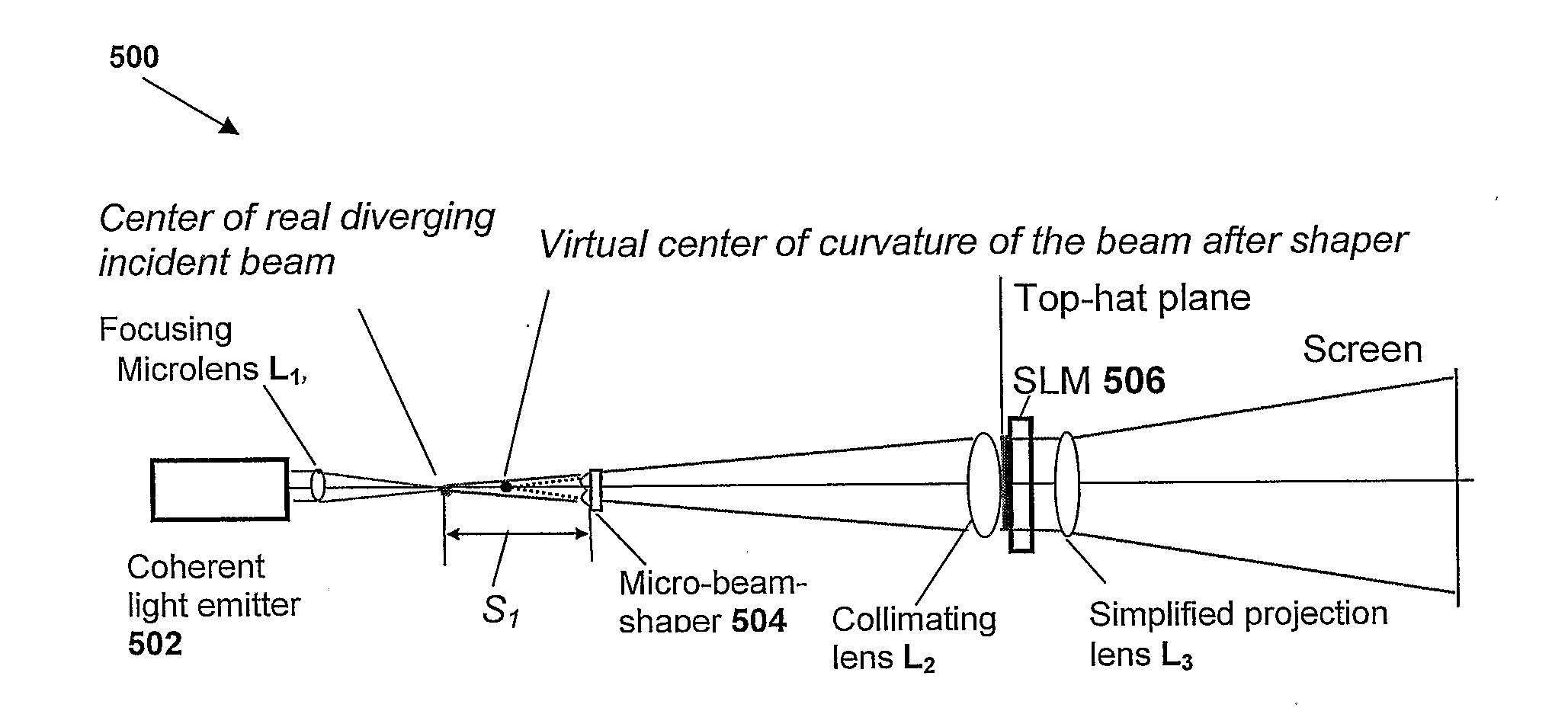
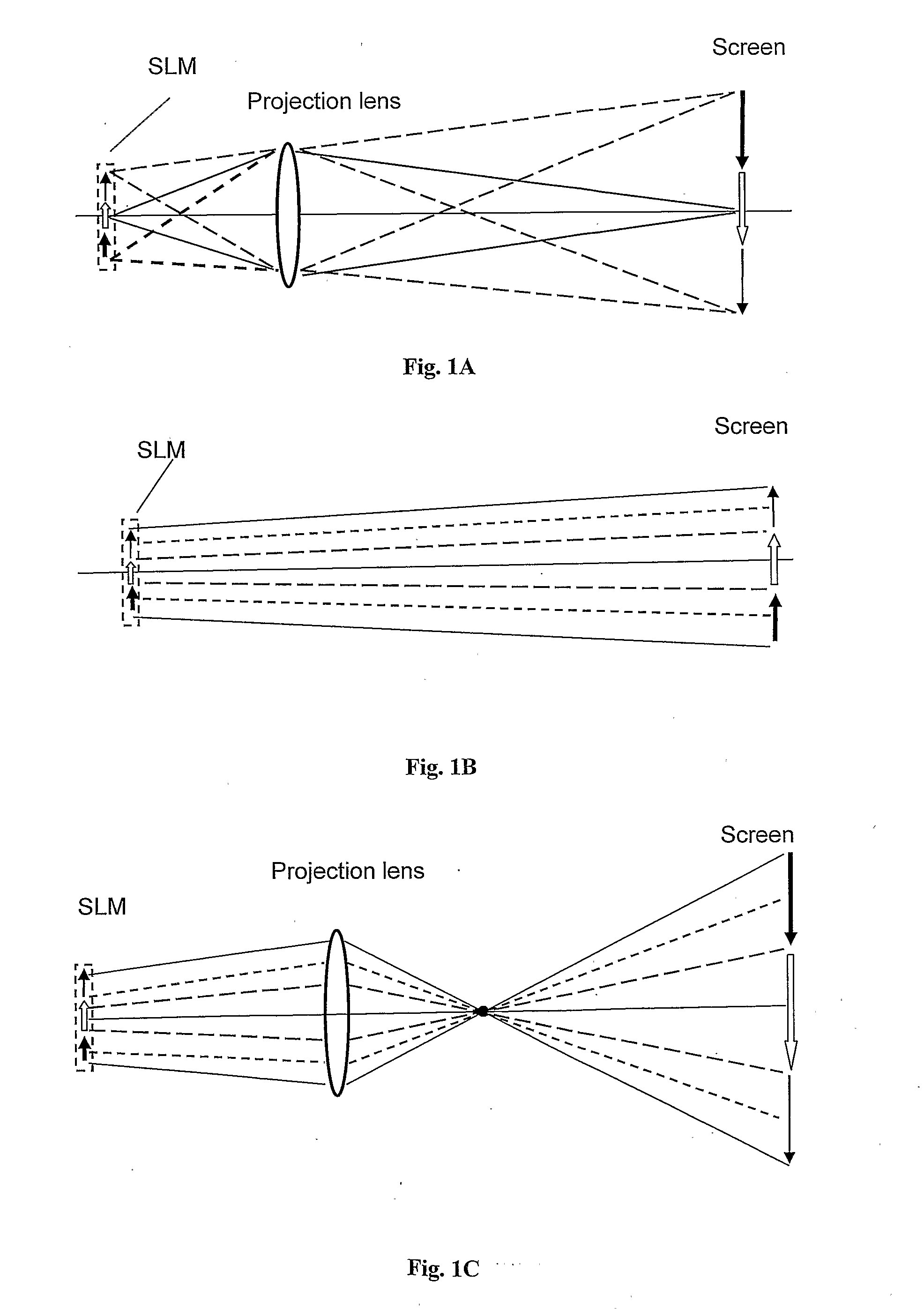
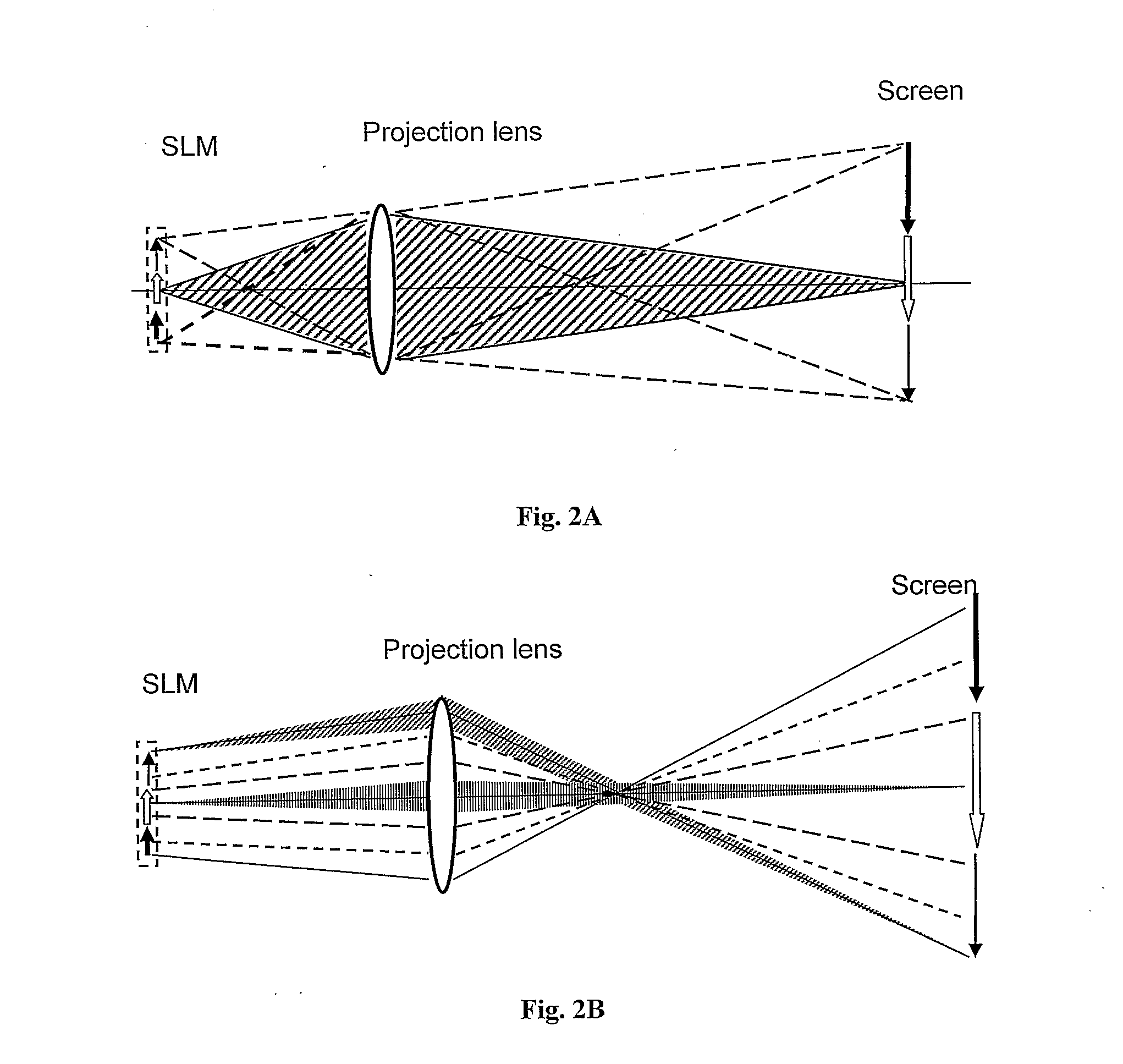
[0033]The projection system of the present invention uses the advantages of coherent imaging. The use of a spatially coherent light source in a projector, especially micro-projector, allows for improving a directional projection of images as compared with that obtainable with using the conventional incoherent projection systems. In this connection, reference is made to FIGS. 1A to 1CFIGS. 1A-1C, illustrating a light propagation scheme for incoherent and coherent imaging setups.

[0034]In FIG. 1A, an object illuminated by incoherent light is imaged onto a screen using a projection lens. As illustrated, every point of the object produces a wide fan of many rays inducing a projection system having high resolution in incoherent imaging. In A system illuminated by a coherent light is commonly unable to provide a wide fan of rays but features interaction between adjacent points of the coherent light image. In a lenslet imaging with coherent light (e.g. geometrical coherent imaging), as illu...


PUM


Abstract

A coherent light source system is presented. The system comprises at least one coherent light emitter producing a coherent light beam, a focusing lens unit, and a beam shaper unit, the beam shaper unit being accommodated between the coherent light emitter and the collimating lens unit being in a front focal plane of the focusing lens unit, thereby providing a substantially uniform profile and high-degree collimation at a desired plane in an optical path of light propagation.

Description

CROSS-REFERENCE TO RELATED APPLICATIONS[0001]This application is a National Phase of International Patent Application No. PCT / IL2008 / 000991, filed Jul. 17, 2008, which claims the benefit of priority from U.S. Provisional Patent Application No. 60 / 950,141, filed 17 Jul. 2007.FIELD OF THE INVENTION[0002]The present invention relates generally to projection systems using laser sources and electro-optical spatial light modulators (SLM), e.g. liquid crystal panels.BACKGROUND OF THE INVENTION[0003]Image projection systems are the essential part of computers, television and cinema systems. Compact projection systems help to display in a user friendly form, the digital contact tapped inside laptop and desktop computers, cellular phones, or compact memory devices. The use of coherent laser sources in an image projection system is disclosed for example in the U.S. Pat. No. 6,494,371. A scanning Red-Green-Blue (RGB) laser beam system is disclosed for example in U.S. Pat. No 6,000,801, and No. ...

Claims


Application Information

Patent Timeline
IPC IPC(8): G02F1/1335F21V5/00F21V9/16G03B21/14
CPCG02B3/0006G02B5/32G02B27/0927G02F2001/133623G03B33/12G03B21/208H04N9/3161H04N9/3197G03B21/2013G03B21/2033H04N9/3108G02F1/133623
Inventor GOLUB, MICHAEL
Owner GOLUB MICHAEL
Why Eureka
Try Eureka