Display apparatus and electronic apparatus with the same

a technology of electronic equipment and display apparatus, applied in the direction of substation/switching arrangement details, substation/switching arrangement boards/panels/desks, instruments, etc., can solve the problems of liquid crystal display panel, display panel itself is extremely fragile, thin transparent substrate provided on the front surface of its display panel, etc., to reduce the breakage of the display apparatus and high mechanical durability

Inactive Publication Date: 2010-07-15
SHARP KK
View PDF3 Cites 32 Cited by
  • Summary
  • Abstract
  • Description
  • Claims
  • Application Information

AI Technical Summary

Benefits of technology

[0013]In view of the conventional problems, preferred embodiments of the present invention provide a display apparatus and a portable electronic apparatus including the display apparatus, which display apparatus has high mechanical durability due to its reduction in breakage of the display apparatus caused by a load placed on a display surface of the display panel and an impact at a time when the display apparatus is dropped.

Problems solved by technology

However, with the mobile apparatus which excels in mobility, and the thin and lightweight portable or stationary flat panel display device, transparent substrates that are provided on a front surface of its display panel is thin.
Thus, the display panel itself is extremely fragile.
Therefore, for example, there is a problem such that when the liquid crystal display device is dropped from a back side of the liquid crystal display device, the liquid crystal display panel 201 may deform or break under impact on the liquid crystal display panel 201 placed on from the driving circuit board 204 side.
Therefore, there is a possibility that the panel may deform or break if only the arrangements of Japanese Unexamined Patent Publication No. 266759 / 2001 (Tokukai 2001-266759) and Japanese Unexamined Patent Publication No. 174206 / 1999 (Tokukaihei 11-174206) are provided.

Method used


Image

  • Display apparatus and electronic apparatus with the same
  • Display apparatus and electronic apparatus with the same
  • Display apparatus and electronic apparatus with the same

Examples


first preferred embodiment

[0093]One preferred embodiment of the present invention is described below with reference to FIGS. 1 through 8. Note that this preferred embodiment does not limit the invention in any way.

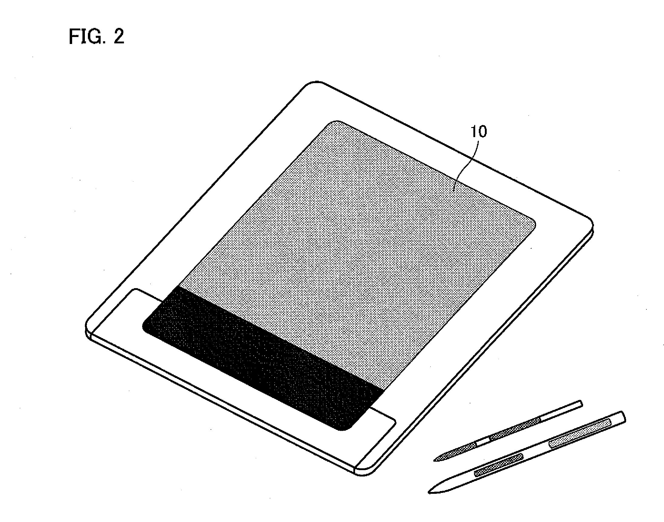
[0094]A liquid crystal display device 10 as a display apparatus of the present preferred embodiment is, for example, incorporated in a portable electronic apparatus such as a tablet personal computer, as illustrated in FIG. 2. However, it is not necessarily limited to this, and the portable electronic apparatus may be, for example, a display for a notebook computer, an information mobile terminal (PDA: Personal Digital Assistant), or a mobile phone.

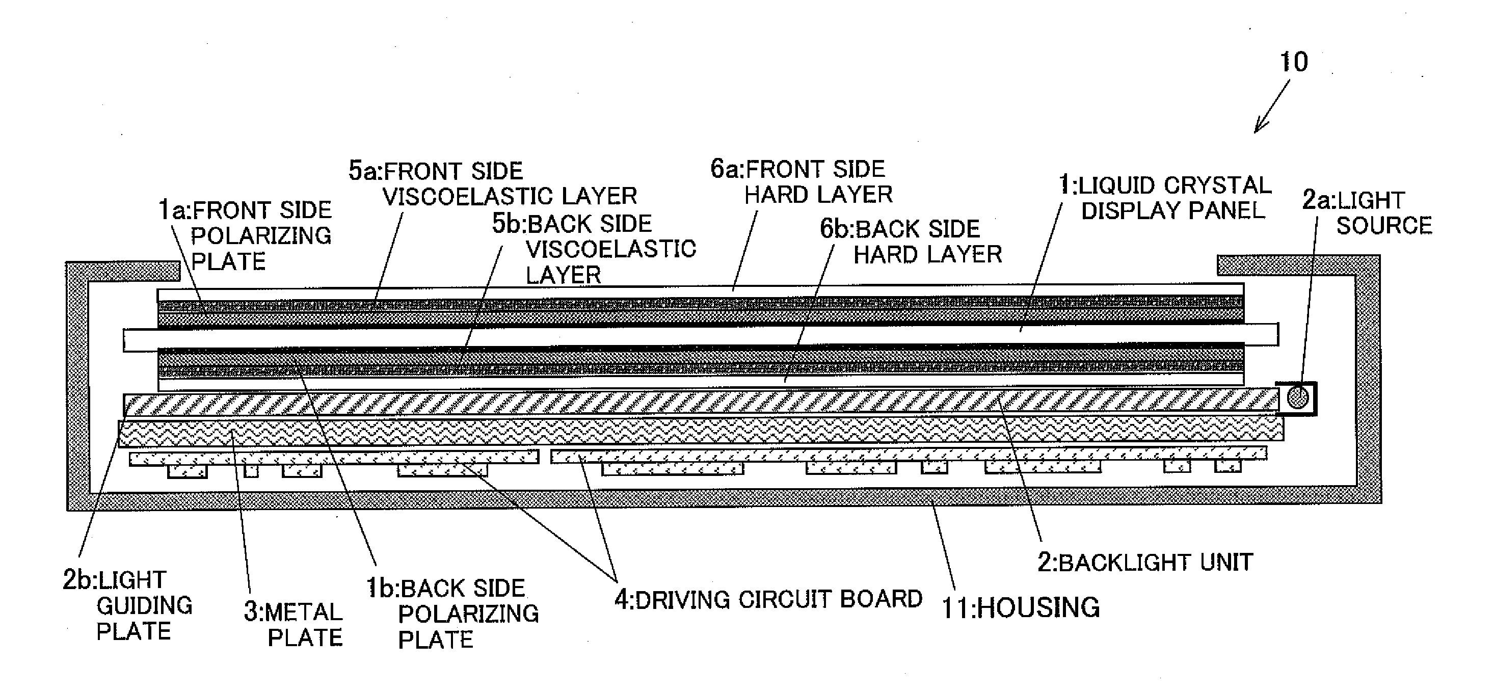
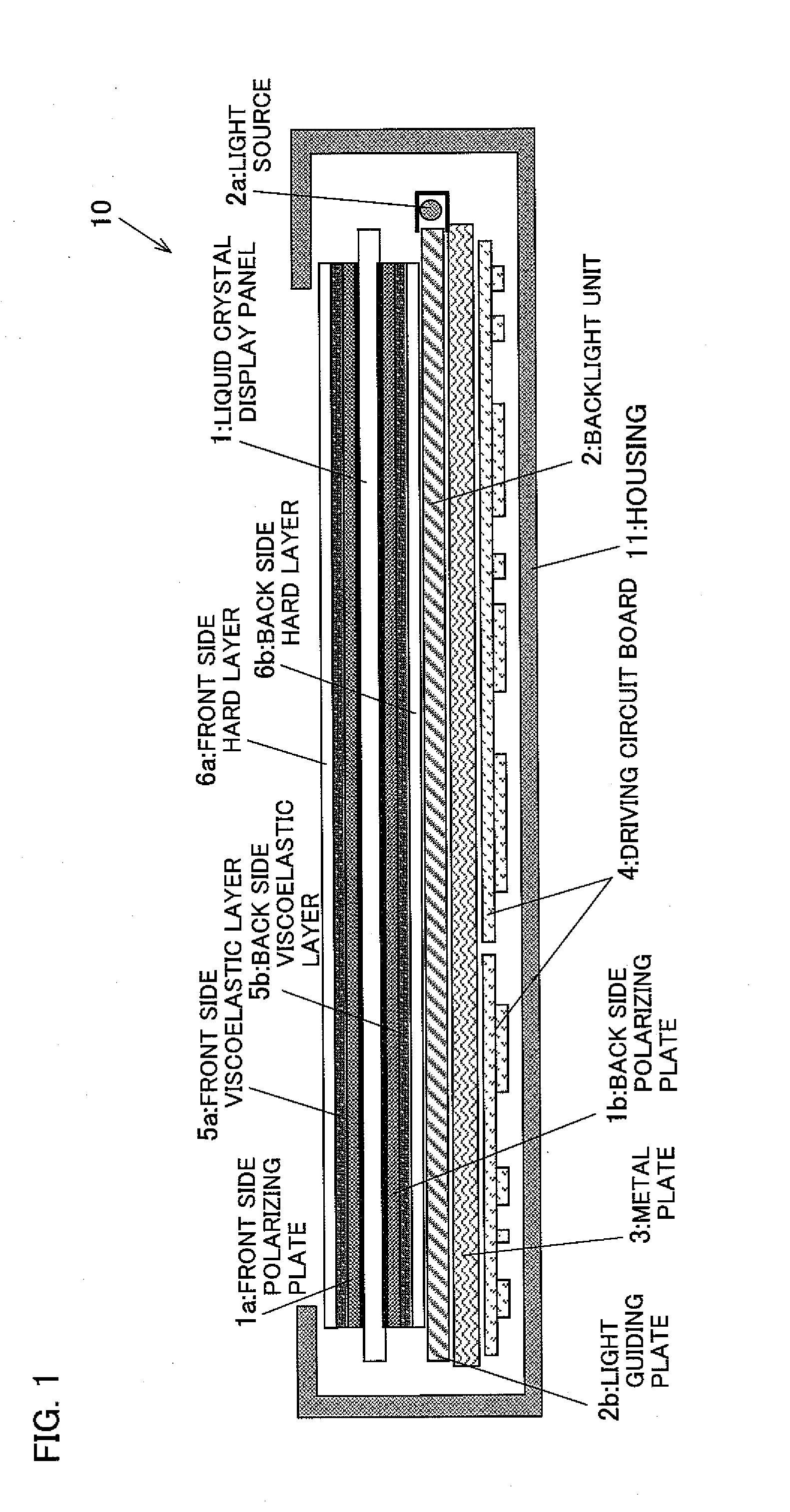
[0095]The following description describes an arrangement of the liquid crystal display device 10. FIG. 1 is a cross sectional view illustrating the arrangement of the liquid crystal display device 10.

[0096]The liquid crystal display device 10, as illustrated in FIG. 1 is, in brief, constructed by stacking, in order from top, a liquid crystal display pane...

example

[0158]The present example carried out a verification experiment for verifying a relationship between breakage and a thickness of the front side viscoelastic layer 5a and the back side viscoelastic layer 5b, of the liquid crystal display panel 1 of First Preferred Embodiment.

[0159]A result thereof is shown in Table 1. Note that, the present experiment introduces a case of an arrangement in which a front side polarizing plate 1a is used instead of the front side hard layer 6a, and a back side polarizing plate 1b is used instead of the back side hard layer 6b, as illustrated in FIGS. 6A and 6B.

TABLE 1Front sideBack sideviscoelastic layerviscoelastic layerBreakage of[Ta] [μm][Tb] [μm]PanelComparative20-1000XExample 1Comparative4000ΔExample 2Comparative2020-40XExample 3Example 15020-40ΔComparative5050XExample 4Example 210020-40◯Example 310050ΔExample 440020-50⊚Comparative50400XExample 5Comparative400400XExample 6

[0160]The front side polarizing plate 1a used as the front side hard layer a...

second preferred embodiment

[0175]Another preferred embodiment of the present invention is described below with reference to FIGS. 9 through 20. Note that, arrangements other than what is explained in the present preferred embodiment is identical to First Preferred Embodiment. For convenience, members which have identical functions to the members illustrated in drawings of First Preferred Embodiment have identical reference numerals, and explanations thereof are omitted.

[0176]A liquid crystal display device 20 of the present preferred embodiment, in addition to the arrangement of the liquid crystal display device 10 of First Preferred Embodiment, is provided with a falling portion 3a and a rising portion 3b along a periphery of a metal plate 3. A lower end of the falling portion 3a and an upper end of the rising portion 3b are in contact with or are fixed to a housing 11 of the liquid crystal display device 20 so that the metal plate 3 does not readily warp, even if a metal plate 3 of a same thickness is used....


PUM

PropertyMeasurementUnit
thickness Taaaaaaaaaaa
heightaaaaaaaaaa
weightaaaaaaaaaa

Abstract

A display apparatus includes a liquid crystal display panel, a front side viscoelastic layer, a front side hard layer, a back side viscoelastic layer, a back side hard layer, a backlight unit, a driving circuit board, and a metal plate. The front side viscoelastic layer that is viscoelastic covers a display surface of the liquid crystal display panel. The front side hard layer has a higher modulus of elasticity than the front side viscoelastic layer. The back side viscoelastic layer that is viscoelastic covers a back surface of the liquid crystal display panel. The back side hard layer has a higher modulus of elasticity than the back side viscoelastic layer. The back side viscoelastic layer has a thickness Tb of not less than about 20 μm, and the front side viscoelastic layer has a thickness Ta and satisfies: Ta/Tb>1 (Tb≠0). Thus, the display apparatus is resistant to breakage caused by a load placed on a display surface of the liquid crystal display panel and an impact when dropped, thereby attaining mechanical durability.

Description

BACKGROUND OF THE INVENTION[0001]1. Field of the Invention[0002]The present invention relates to a display apparatus such as a liquid crystal display device, suitable as a display section of a portable electronic apparatus or a stationary electronic apparatus, and an electronic apparatus including the display apparatus. More specifically, the present invention is related to strength reinforcement of, for example, a slim flat panel display device. Further, the present invention relates to reinforcement in strength of a stationary electronic apparatus including a large-sized liquid crystal display device such as a liquid crystal TV (television) or the like as one example, when carrying or handling the stationary electronic apparatus.[0003]2. Description of the Related Art[0004]In recent years, a flat panel display device such as a liquid crystal display device and an electroluminescence display device (hereinafter referred to as “EL display device”) has been frequently used as a displ...

Claims


Application Information

Patent Timeline
Patent Type & Authority Applications(United States)
IPC IPC(8): G02F1/1333
CPCG02F1/133308G02F2201/503G02F2201/50
Inventor ICHIOKA, HIDEKIYAMAMOTO, TOMOHIKO
Owner SHARP KK
Why Eureka
Try Eureka