Optical film
- Summary
- Abstract
- Description
- Claims
- Application Information
AI Technical Summary
Problems solved by technology
Method used
Image

Examples
example 1
Preparing a “Wide-Range” Cholesteric Liquid Crystal Layer
1-1 Preparing a Single Layer Film
[0062]Reactive cholesteric liquid crystals of 90032 (Wacker) and nematic liquid crystals of E7 (Merck) are mixed in a ratio 2:1. After a photoinitiator IG184 0.6% is added, the mixture is filled into a empty test cell of 10 μm cell gap. The cholesteric liquid crystal cell is then exposed to UV light with intensity of 100 uW / cm2 at 92° C. for 15 minutes for solidification. Its selective reflection wavelength range is 400 to 700 nm measured by a Perkin-Elymer UV / VIS, and the film thickness is 10 μm.
1-2 Preparing Multi-Layer Films
1-2-1 Continuous Coating Method
[0063]By using a spin-coating machine, a solution with 30 wt % of cholesteric liquid crystals HELISOL® 0142R is added with 1% of an initiator I-907 and coated on a glass substrate that has undergone annealing treatment. The solvent is removed at 90° C. Then, the coating layer is exposed to UV light at 105° C. and the spinning speed is well c...
example 2
Preparing a “Narrow-Range” Cholesteric Liquid Crystal Layer
[0068]By using a spin-coating machine, a solution of 30 wt % of cholesteric liquid crystals HELISOL® 0250R and 1% of an initiator I-907 is coated on a PET substrate that has undergone annealing treatment. The solvent is removed at 90° C. Then the coating layer is exposed to UV light at 105° C., thereby obtaining a cholesteric liquid crystal film with a thickness of 2˜10 μm Its reflection wavelength is in the range of green light.
[0069]Those who are skilled in the art can utilize the same method but different liquid crystal material or different process conditions to form cholesteric liquid crystal layers with reflection wavelength in the range of other colors. For example, by replacing the cholesteric liquid crystal solution with HELISOL® 0359R, under the same conditions the final product is a cholesteric liquid crystal film with the reflection wavelength in the range of red light.
example 3
Preparing a Multi-Functional Optical Film of the Present Invention
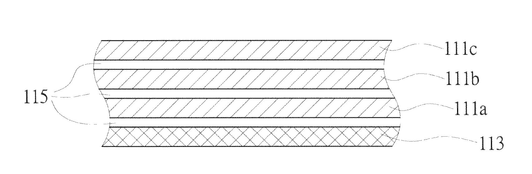
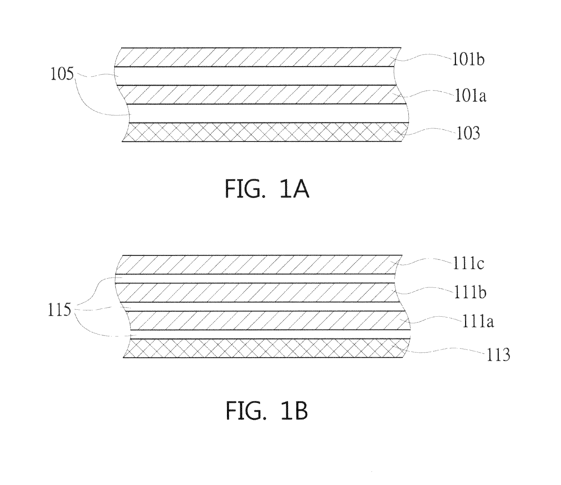
3-1 The Structure Having Two Layers of Cholesteric Liquid Crystal Layers
3-1-1 The Structure Having Two Layers of Wide-Range Cholesteric Liquid Crystal Layers
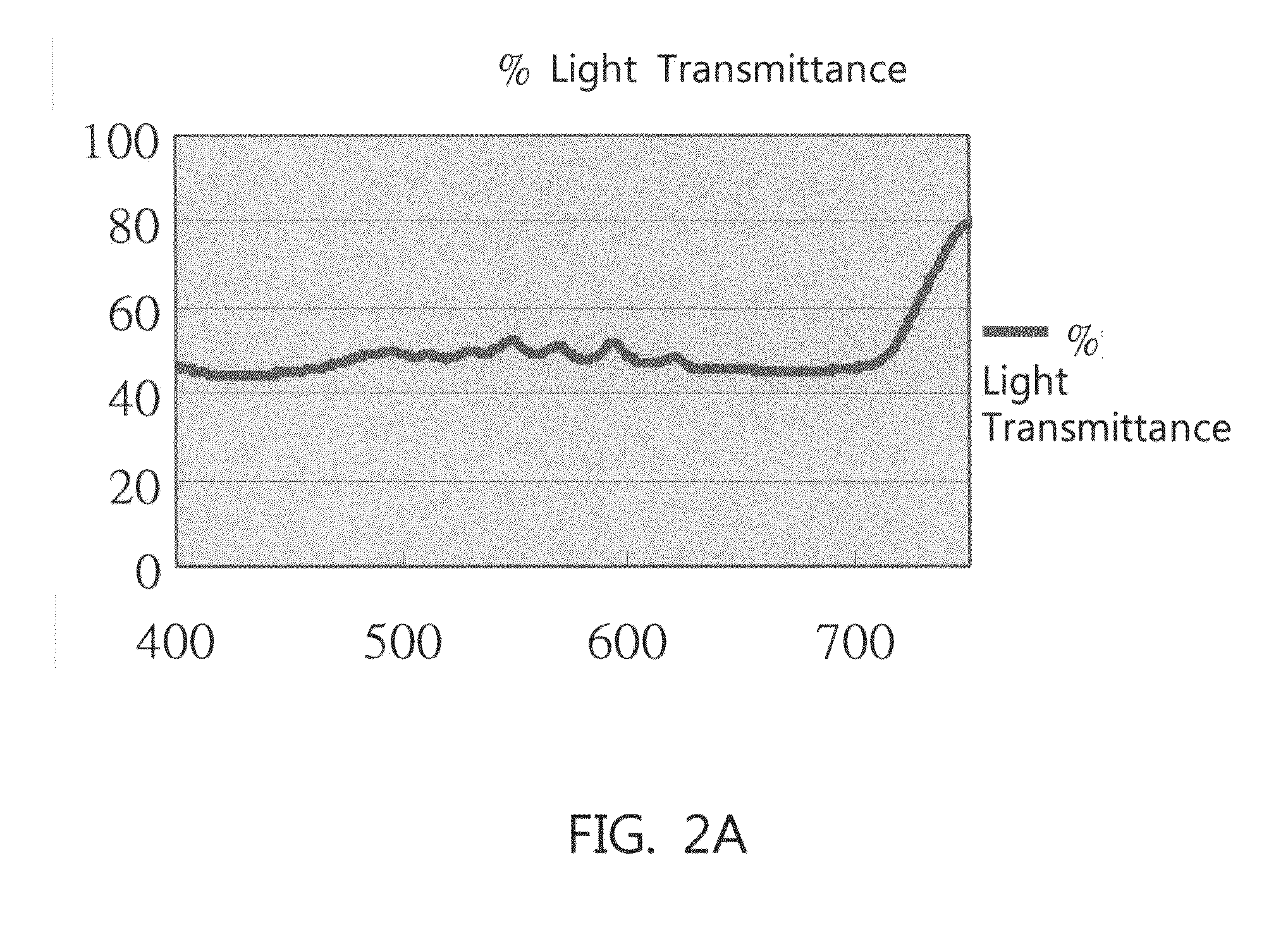
[0070]Two single layer films obtained through Example 1-2-1 are bound together via an optical adhesive. The optical adhesive is purchased from Sokan Chemical (acrylic glue series, with the refractive index ranging from 1.3 to 1.65), and the adhesive has a thickness of 25 μm. Next, a substrate is removed so as to expose a surface of the laminated cholesteric liquid crystal film. Further, a quarter-wavelength retardation plate (Tejin Chemical, TT / S / W series) is bound thereto, thereby obtaining an optical film of the present embodiment.
[0071]The polarized separated wavelength range is measured by an UV / Vis spectrometer (Perkin-Elymer Lamda-900 equipped with a polarized light measuring package) and the result is shown in FIG. 2A.
[0072]The method for measuring the coll...
PUM
 Abstract
Description
Claims
Application Information
 - Generate Ideas
- Intellectual Property
- Life Sciences
- Materials
- Tech Scout
- Unparalleled Data Quality
- Higher Quality Content
- 60% Fewer Hallucinations
Browse by: Latest US Patents, China's latest patents, Technical Efficacy Thesaurus, Application Domain, Technology Topic, Popular Technical Reports.
© 2025 PatSnap. All rights reserved.Legal|Privacy policy|Modern Slavery Act Transparency Statement|Sitemap|About US| Contact US: help@patsnap.com