Endoscope system for fluorescent observation

a fluorescent observation and endoscope technology, applied in the field of endoscopes, can solve the problems of remarkably adverse factors, inapplicability of conventional techniques focusing on morphologic changes in cells for determining the presence of cancer, and the fact that the tissues to be observed are within a living body

Inactive Publication Date: 2005-02-03
OLYMPUS CORP
View PDF4 Cites 160 Cited by
  • Summary
  • Abstract
  • Description
  • Claims
  • Application Information

AI Technical Summary

Problems solved by technology

However, cancer cells in the earliest stage show only meager morphologic changes from normal cells, and thus, conventional techniques that focus primary on morphologic changes in cells for determining the presence of cancer are not applicable for detecting cancer in the earliest stage.
In addition, living tissue scatters light in a sufficiently intense manner that the living tissue layer above the cancerous region blocks observation of the cancer.
This becomes a remarkably adverse factor in solving the problem of detecting cancer in the earliest stage.
Of course, the fact that the tissues to be observed are within a living body is also an adverse factor.
However, the resolution of these devices is not yet sufficient to enable cancer to be detected in its earliest stage or to enable a di...

Method used


Image

  • Endoscope system for fluorescent observation
  • Endoscope system for fluorescent observation
  • Endoscope system for fluorescent observation

Examples


first embodiment

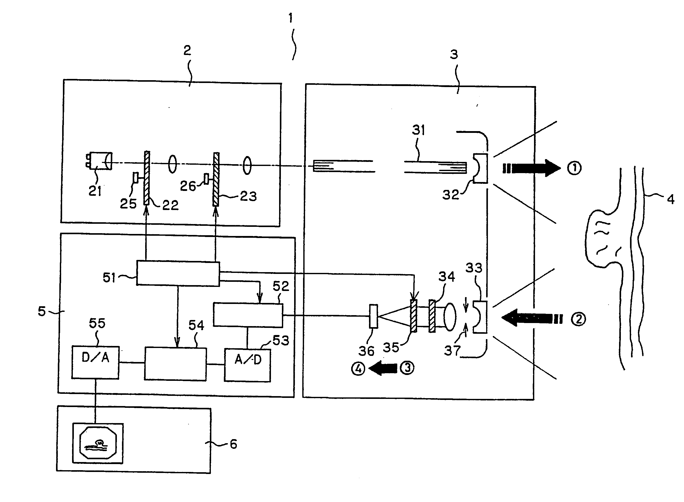
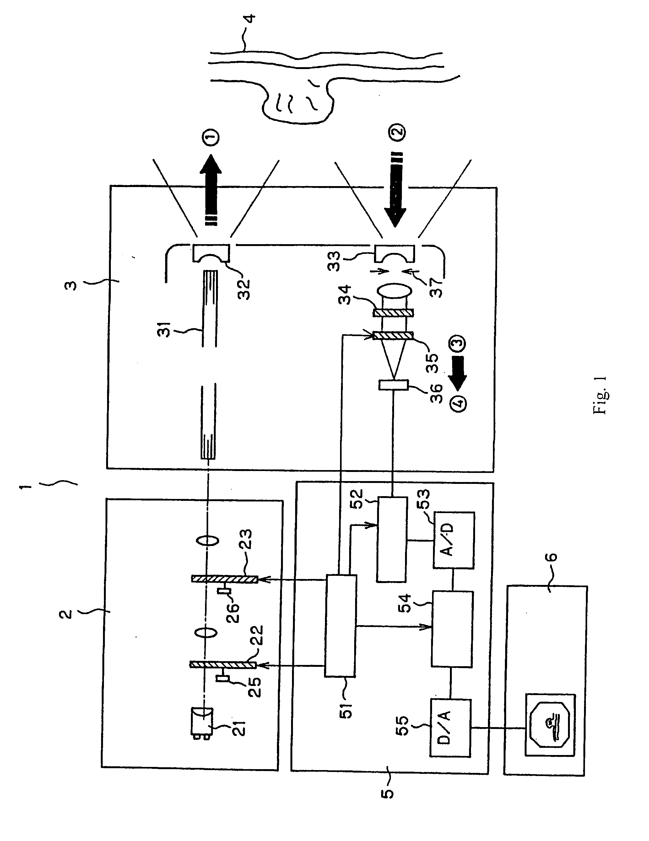
FIG. 1 shows the entire structure of the endoscope system according to the present invention. In FIG. 1, an endoscope system 1 is formed of a light source system 2, an endoscope 3, a processor 5, and a monitor 6. This embodiment is characterized by having a structure that separates and detects plural fluorescent wavelengths within the endoscope tip.

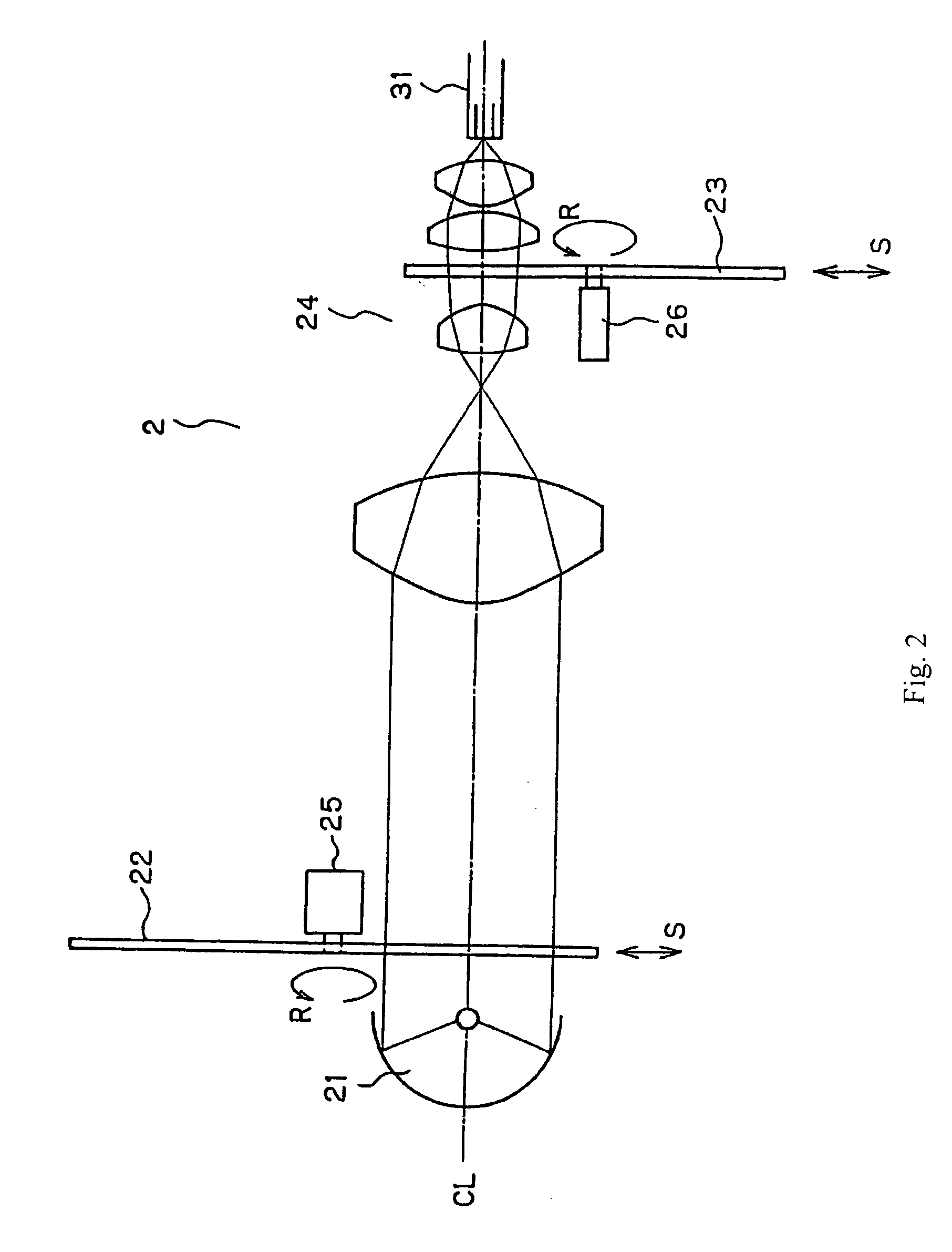
FIG. 2 is an illustration that shows the structure of the light source optical system in the light source system 2 which can be used to detect fluorescent labels such as quantum dots (having, for example, emission spectra as shown in FIG. 38) that have previously been introduced into living tissue 4 to be examined with the endoscope system of the present invention. The light source optical system 2 is formed of a light source 21, a turret 22 provided with plural optical filters, and a rotational disk 23 provided with plural optical filters that are arranged concentrically. The light source 21 can be a Xenon lamp that includes light wavele...

second embodiment

FIGS. 40-42 show alternative embodiments of the entire structure of the endoscope system according to the present invention wherein the structure that separates and detects plural fluorescent wavelengths is positioned other than in the endoscope tip. As the individual components are numbered identically with those of FIG. 1, only the differences will be now be described. FIG. 40 shows the overall structure of an endoscope system according to the present invention, characterized by having the components that separate and detect plural fluorescent wavelengths within the endoscope tip of the type that uses an optical fiber (fiberscope). Whereas in FIG. 1 the optical elements including the excitation light cut-off filter 34 are positioned just after the objective lens 33, in FIG. 40 a fiber bundle (a so-called image guide fiber bundle) is arranged just after the objective lens, and an ocular lens is provided at the exit side of the fiber bundle. The detection optical elements, which hav...

embodiment 1

FIG. 43 shows another embodiment of the present invention. Only the differences with regard to FIG. 43 will be described as compared to FIG. 39. In this embodiment, a tunable filter 35 and a detector 36 are used as in FIG. 1 as a wavelength separation element for separating fluorescent wavelengths emitted by the fluorescent labels in lieu of using a dichroic prism 125 and the three CCDs 124a, 124b, and 124c shown in FIG. 39. Furthermore, a color CCD 202 is used in lieu of the second dichroic prism 129 for detecting visible light components and the plural-circuit-board camera that uses the three CCDs 126, 127, and 128. Thus, the number of CCDs used at the camera head can be significantly reduced and this not only makes for a more compact design but also the endoscope has reduced cost. Also with this structure, the same detection ability of visible and fluorescent light as the endoscope system having the structure shown in FIG. 39 can be obtained. The color CCD 202 can be replaced by ...


PUM


Abstract

An endoscope system is disclosed for detecting fluorescent light emitted in the near-infrared region by a plurality of fluorescent labeling materials introduced into a living tissue. An illumination system generates illumination light in the wavelength range 600 nm-2000 nm which serves as excitation light for the plurality of fluorescent labeling materials, and a detection system that can separately detect different ones of the plurality of fluorescent light emissions that are emitted at different wavelengths from among the plurality of fluorescent labeling materials is provided. The endoscope system may include a conventional-type endoscope having an insertion section, or a capsule endoscope that wirelessly transmits image data. By superimposing the image data obtained using reflected light in the visible region and fluorescent light emitted by the fluorescent labeling materials, improved diagnostic capabilities are provided.

Description

This application claims the benefit of priority of JP 2003-172361, filed in Japan on Jun. 15, 2003, and of JP 2004-176198, filed in Japan on Jun. 14, 2004, the subject matters of which are hereby incorporated by reference. BACKGROUND OF THE INVENTION Prior art endoscopes have conventionally been used in diagnosis and treatment where a fluorescent substance having an affinity to a lesion, such as cancer, has been previously administered into a subject's body and excitation light that excites the fluorescent substance is then irradiated onto tissue of the subject so that fluorescent emissions from the fluorescent substance that deposits at the lesion can be detected. For example, Japanese Laid-Open Patent Application H10-201707 describes a prior art endoscope wherein indocyanine green derivative labeled antibodies have been previously introduced into the living tissue. The lesions then emit fluorescent light when excited by infrared light, with the infrared light being readily tran...

Claims


Application Information

Patent Timeline
IPC IPC(8): A61B1/04
CPCA61B1/041A61B1/0638A61B1/0669A61B1/043A61B1/0646A61B1/00186A61B1/0655
Inventor MATSUMOTO, SHINYAHASEGAWA, AKIRA
Owner OLYMPUS CORP
Why Eureka
Try Eureka