Pickup device

Inactive Publication Date: 2010-07-15
PIONEER CORP
View PDF7 Cites 11 Cited by
  • Summary
  • Abstract
  • Description
  • Claims
  • Application Information

AI Technical Summary

Benefits of technology

[0012]When changes in FES level of FIG. 5 (1)-(5) are plotted as points 1-5 on a graph against the displacement (defocus) relative to a track position, a so-called S-curve characteristic shown in FIG. 6 is obtained. As seen from FIGS. 5, 6, as the line image becomes thinner in FIG. 5 (1), (5), the swing of the focus error signal becomes larger, resulting in a good error signal.
[0019]Accordingly, an object of the present invention is to provide a pickup device that can reduce an offset occurring at the boundary between an already recorded area and an unrecorded area with suppressing the adverse effect of the general astigmatism method on the focus error signal to a minimum.Means for Solving the Problem

Problems solved by technology

The servo control uses servo error signals (push-pull signals such as a focus error signal and a tracking error signal), in which noise due to external disturbance is mixed causing the offset of the signals, hence presenting a problem.

Method used


Image

  • Pickup device
  • Pickup device
  • Pickup device

Examples


Embodiment Construction

[0073]Optical pickups according to embodiments of the present invention will be described below with reference to the drawings.

[0074]FIG. 8 shows schematically the configuration of an optical pickup device 3.

[0075]The optical pickup device 3 comprises a semiconductor laser 31 as a light source, a beam splitter 33, a collimator lens 34 for collimating diverging light to be parallel light, an objective lens OB, a hologram element 37 as a dividing element for dividing and deflecting transmitted light into a plurality of light beams, a detection lens 38, and a photo detector 40 for performing photoelectric conversion.

[0076]Light from the semiconductor laser 31 is made to be parallel light by the collimator lens 34 and is incident on the beam splitter 33 to be reflected to an optical disc 1. The light is focused onto a recording surface of the optical disc 1 by the objective lens OB, and reflected light passes through the objective lens OB again to become parallel light, which passes thr...


PUM


Abstract

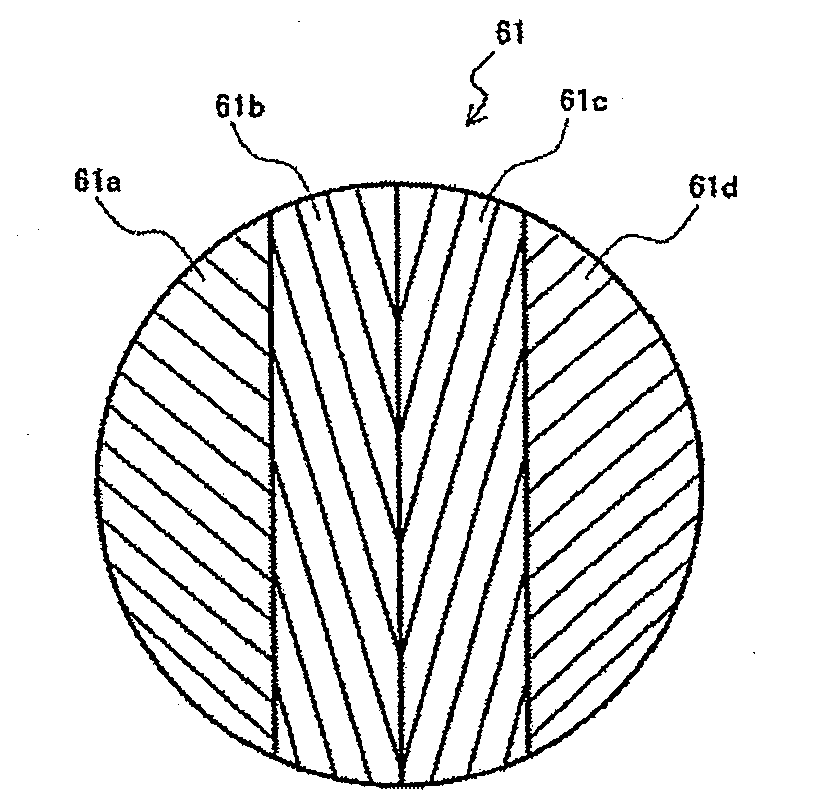
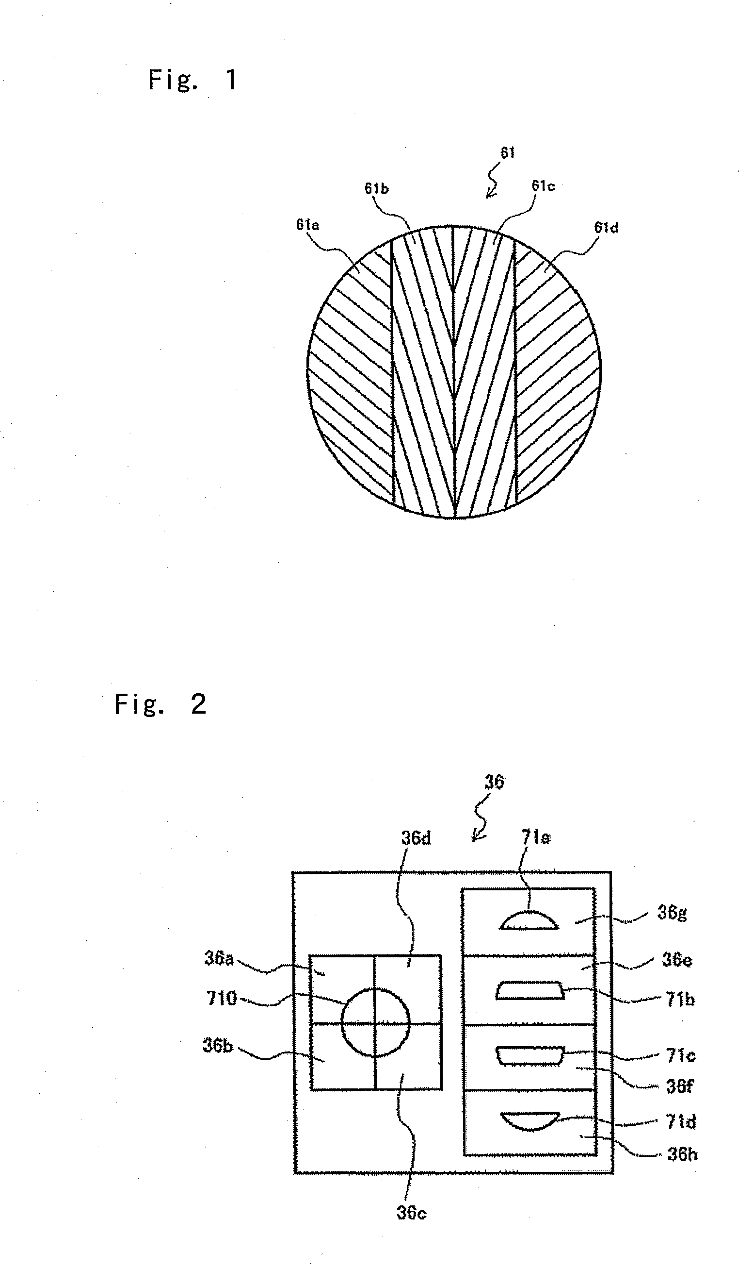
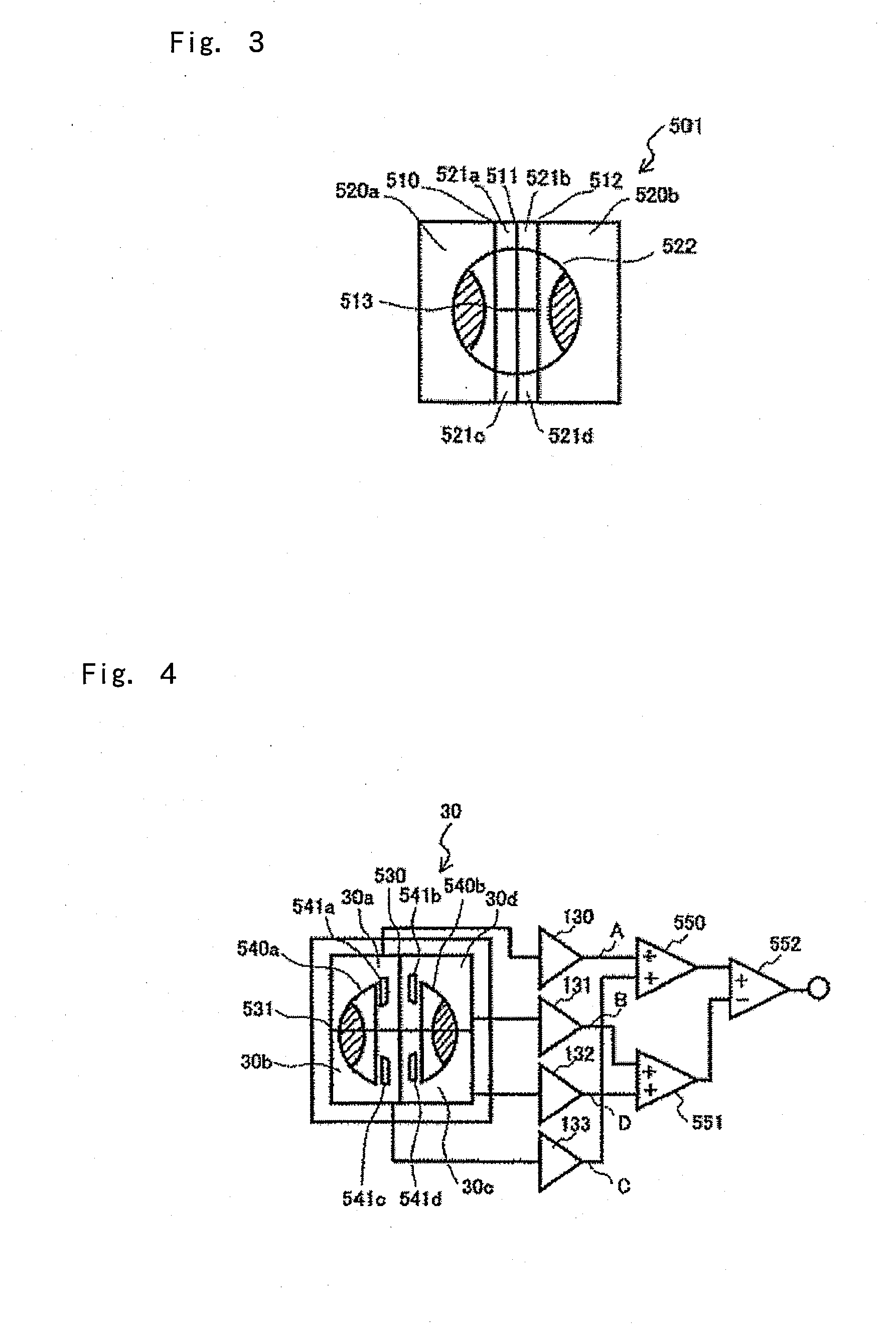
A pickup device which, focusing a ray bundle on a track of a recording surface of an optical recording medium to form a light spot, comprises a detection optical system including a photo detector to receive return light reflected from the light spot via an objective lens and perform photoelectric conversion. The photo detector has at least two photoreceptor sections positioned axis-symmetrical with respect to a detection-side division line extending through an optical axis of the return light and parallel to the track. A dividing element placed in an optical path between the photo detector and the objective lens includes at least two inner divided areas positioned axis-symmetrical with respect to a deflection-side division line extending through the optical axis of the return light and parallel to the track, and at least two outer divided areas positioned sandwiching the inner divided areas and axis-symmetrical with respect to the deflection-side division line. The inner divided areas are formed such that parts of a light beam from the other region than overlap regions, divided axis-symmetrically along the deflection-side division line, are exchanged in position across the detection-side division line and directed to the photoreceptor sections of the photo detector so as to be axis-symmetrical with respect to the detection-side division line.

Description

TECHNICAL FIELD[0001]The present invention relates to an optical pickup device for a recording and reproducing apparatus for optical recording media such as optical discs and particularly to an optical pickup device that controls position for optimum focusing of a ray bundle onto a recording surface of an optical recording medium such as an optical disc having multiple recording layers laid one on top of another using an astigmatism method.BACKGROUND ART[0002]In these years, optical discs are widely used as means for recording and reproducing data such as video data, voice data, and computer data. For example, high density recording optical discs called Blu-ray™ Disc have been put to practical use. With further high density recording optical discs, in order to read out information from one surface side with use of an optical pickup device, a ray bundle needs to be condensed to be focused on a track on a recording surface of interest (in-focus position or optimum focusing position), ...

Claims


Application Information

Patent Timeline
IPC IPC(8): G11B7/00G11B7/13G11B7/135
CPCG11B7/0901G11B7/0909G11B2007/0013G11B7/1353G11B7/133
Inventor SATO, MAKOTOOGASAWARA, MASAKAZUYANAGISAWA, TAKUMA
Owner PIONEER CORP
Why Eureka
Try Eureka