Optical communication system and method for operating the same

a communication system and optical communication technology, applied in the field of optical communication systems and methods for operating the same, can solve the problems of increasing the communication interruption time of each onu, increasing the expected waiting time, and increasing the signal processing load, so as to increase the number of slave stations, suppress the increase in signal interruption time accompanying the distance extension, and extend the communication distance

Inactive Publication Date: 2010-07-15
HITACHI LTD
View PDF2 Cites 19 Cited by
  • Summary
  • Abstract
  • Description
  • Claims
  • Application Information

AI Technical Summary

Benefits of technology

[0008]By inserting the EB into the trunk optical fiber, the communication distance can be more extended than that in the conventional PON, and so an ONU of a subscriber at a remote location can be accommodated in the same OLT, and the number of ONUs accommodated by the OLT can be increased easily. Namely, the ONU accommodation efficiency of the OLT can be improved. On the other hand, as the communication distance increases, the time of communicating with the ONU at a remote location (transmission delay time) increases, and the number of the ONUs also increases, so that at the OLT, not only the signal waiting time but also the signal processing load increases. For these reasons, there is the possibility that the communication time assigned to each ONU will decrease. Specifically, when performing the ranging for measuring the communication distance (transmission delay time) between the OLT of PON and an arbitrary ONU (in many cases, a new ONU additionally connected to the OLT), because of the fact that the OLT waits for a response to the ranging from the ONU, all of the ONUs which have already been connected for operating must interrupt the communication, and by inserting the EB, an expected waiting time increases, followed by an increase in communication interruption time of each ONU. In other words, the increase of the communication interruption time at the ONU in operation has an influence upon the quality of the signal required of the real time property and makes complicated the process for assigning communication capacity (bandwidth) to each ONU based on the DBA (Dynamic Bandwidth Assignment) to all ONUs, decreases the bandwidth assignment, and increases the waiting time for the signal transmission.
[0009]Accordingly, even if an EB is introduced into the PON to extend the communication distance between an OLT and an ONU and to increase the number of accommodated ONUs, there is a demand for providing a PON which can suppress generation of the aforementioned problem that in the OLT, the signal process load increases, that in each ONU, the signal transmission waiting time increases, the transmission signal bandwidth decreases or the quality of transmission signal is degraded, and preferably which has the same communication quality as that of the conventional PON. Specifically, an object of the present invention is to provide a PON which can suppress generation of the aforementioned problem even if the ranging necessary for the PON is performed, a method for controlling the PON and a method for ranging.
[0018]According to the present invention, even if the relay unit is introduced into the optical communication system (PON) to extend the communication distance between the master station and the slave station and to increase the number of the slave stations to be accommodated, the ranging process is separated into two process, and in operation, only one of the two ranging process is performed, and the interruption time of signals from the slave station due to ranging depends on only the maximum distance from the relay unit to the slave station, whereby an increase in signal interruption time accompanying the distance extension can be suppressed. Accordingly, the present invention can suppress the phenomenon such as an increase in the signal processing load in the master station, and an increase in the signal transmission waiting time, an increase in signal transmission waiting time / a decrease in transmission signal bandwidth or a degradation in the quality of the transmission signal on the slave station side.

Problems solved by technology

On the other hand, as the communication distance increases, the time of communicating with the ONU at a remote location (transmission delay time) increases, and the number of the ONUs also increases, so that at the OLT, not only the signal waiting time but also the signal processing load increases.
Specifically, when performing the ranging for measuring the communication distance (transmission delay time) between the OLT of PON and an arbitrary ONU (in many cases, a new ONU additionally connected to the OLT), because of the fact that the OLT waits for a response to the ranging from the ONU, all of the ONUs which have already been connected for operating must interrupt the communication, and by inserting the EB, an expected waiting time increases, followed by an increase in communication interruption time of each ONU.
In other words, the increase of the communication interruption time at the ONU in operation has an influence upon the quality of the signal required of the real time property and makes complicated the process for assigning communication capacity (bandwidth) to each ONU based on the DBA (Dynamic Bandwidth Assignment) to all ONUs, decreases the bandwidth assignment, and increases the waiting time for the signal transmission.
Meanwhile, even in the method of inserting the EB into the branching optical fiber, the same problem takes place in connection with an ONU communicating via the EB.

Method used


Image

  • Optical communication system and method for operating the same
  • Optical communication system and method for operating the same
  • Optical communication system and method for operating the same

Examples


Embodiment Construction

[0034]Hereinafter, configuration and action of a PON according to the present invention will be described with reference to the accompanying drawings as an example of configuration and action of a G-PON stipulated by the ITU-T recommendation G. 984.3.

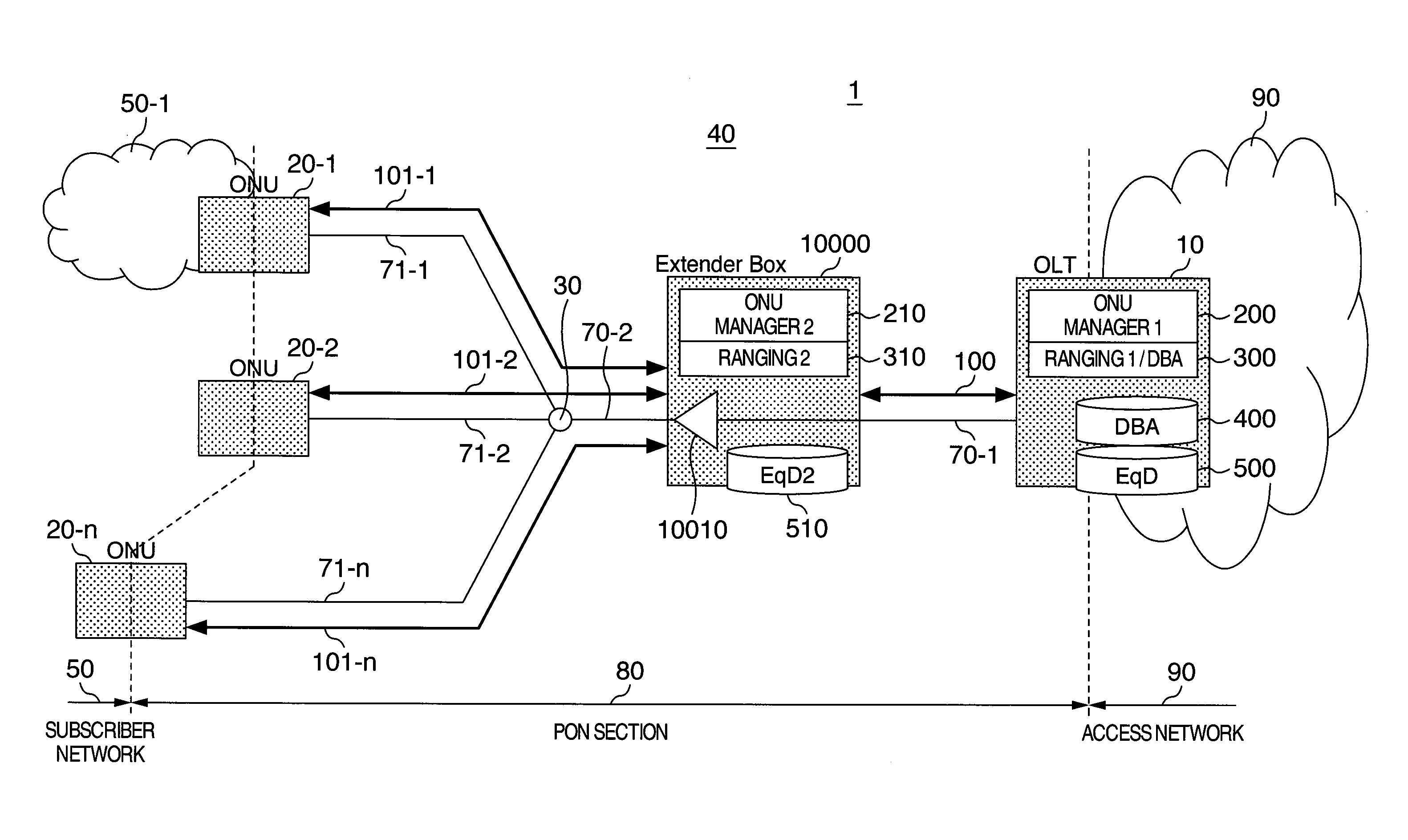
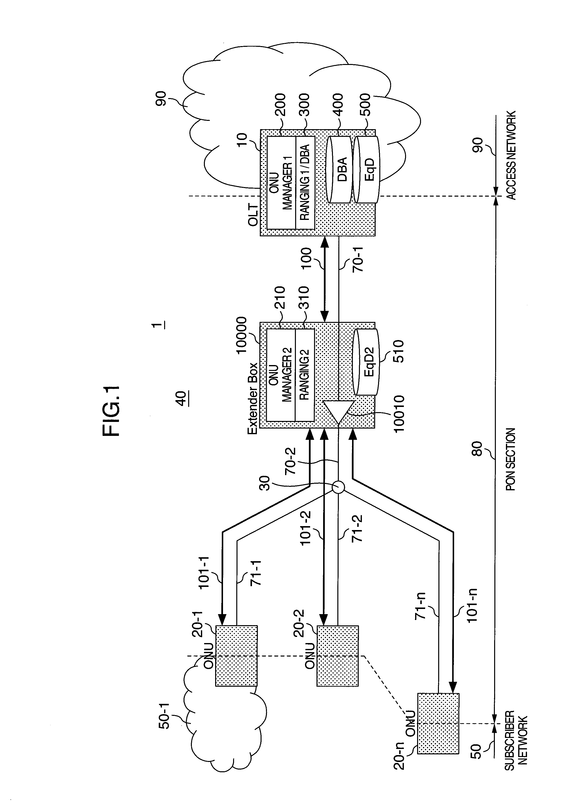
[0035]FIG. 1 is a diagram illustrating a configuration example of an optical access network using a PON according to the present invention, where an EB is inserted in a trunk optical fiber of the PON.

[0036]In a PON 40 having an office side unit (OLT) 10, a plurality of subscriber units (ONUs) 20-1 to 20-n, an optical splitter 30, a trunk optical fiber 70, a plurality of branching optical fibers 71-1 to 71-n and a signal relay unit (EB) 10000 inserted between sections 70-1 and 70-2 on the way of the trunk optical fiber 70, an optical access network 1 is a network for connecting the individual ONUs 20 (20-1 to 20-n) to subscriber networks 50 (or terminals such as PCs or telephones, as a typical example of which only a subscriber network 5...


PUM


Abstract

An optical communication system has a master station and a plurality of slave stations connected thereto via an optical fiber network, which is provided with an optical splitter and a relay unit which relays signals transmitted / received between the master station and the plurality of slave stations. The master station includes a first controller for performing ranging between the master station and the relay unit, and the relay unit includes a second controller for performing ranging between the relay unit and the plurality of slave stations. The master station determines, on the basis of the results of ranging performed by the first and second controllers as well as reports from the slave stations, timings for the slave stations to transmit signals to the master station, and receives signals multiplexed through the optical fiber network from the slave stations.

Description

INCORPORATION BY REFERENCE[0001]The present application claims priority from Japanese application JP2009-003036 filed on Jan. 9, 2009, the content of which is hereby incorporated by reference into this application.BACKGROUND OF THE INVENTION[0002]The present invention relates to the configuration of an optical communication system in which a plurality of subscriber units share an optical transmission line and a method for operating the system, and also relates to a system extension such as an extension of the transmission distance and an increase in the number of subscribers to be accommodated.[0003]As the need for the communication utilizing the broadband increases, with respect to the access line dedicated to users, a large-capacity access line using optical fibers has been substituting for the access technique based on the telephone line such as DSL (Digital Subscriber Line). At present, in view of costs for line construction and maintenance management, the PON (Passive Optical N...

Claims


Application Information

Patent Timeline
Patent Type & Authority Applications(United States)
IPC IPC(8): H04B10/08H04L12/44
CPCH04J3/0652H04J3/0682H04Q2011/009H04Q2011/0081H04Q11/0067
Inventor MIZUTANI, MASAHIKOYAJIMA, YUSUKE
Owner HITACHI LTD
Why Eureka
Try Eureka