
Method and apparatus for characterizing a circuit coupled to an AC line

a circuit coupled to an ac line and characterization method technology, applied in the field of power systems, can solve the problems of increasing the cost of fossil energy currently being used to generate electricity, not being economical choice for solar panels, and rapidly depleting fossil energy reserves

Active Publication Date: 2010-07-22
ENPHASE ENERGY
View PDF4 Cites 60 Cited by
  • Summary
  • Abstract
  • Description
  • Claims
  • Application Information

AI Technical Summary

Benefits of technology

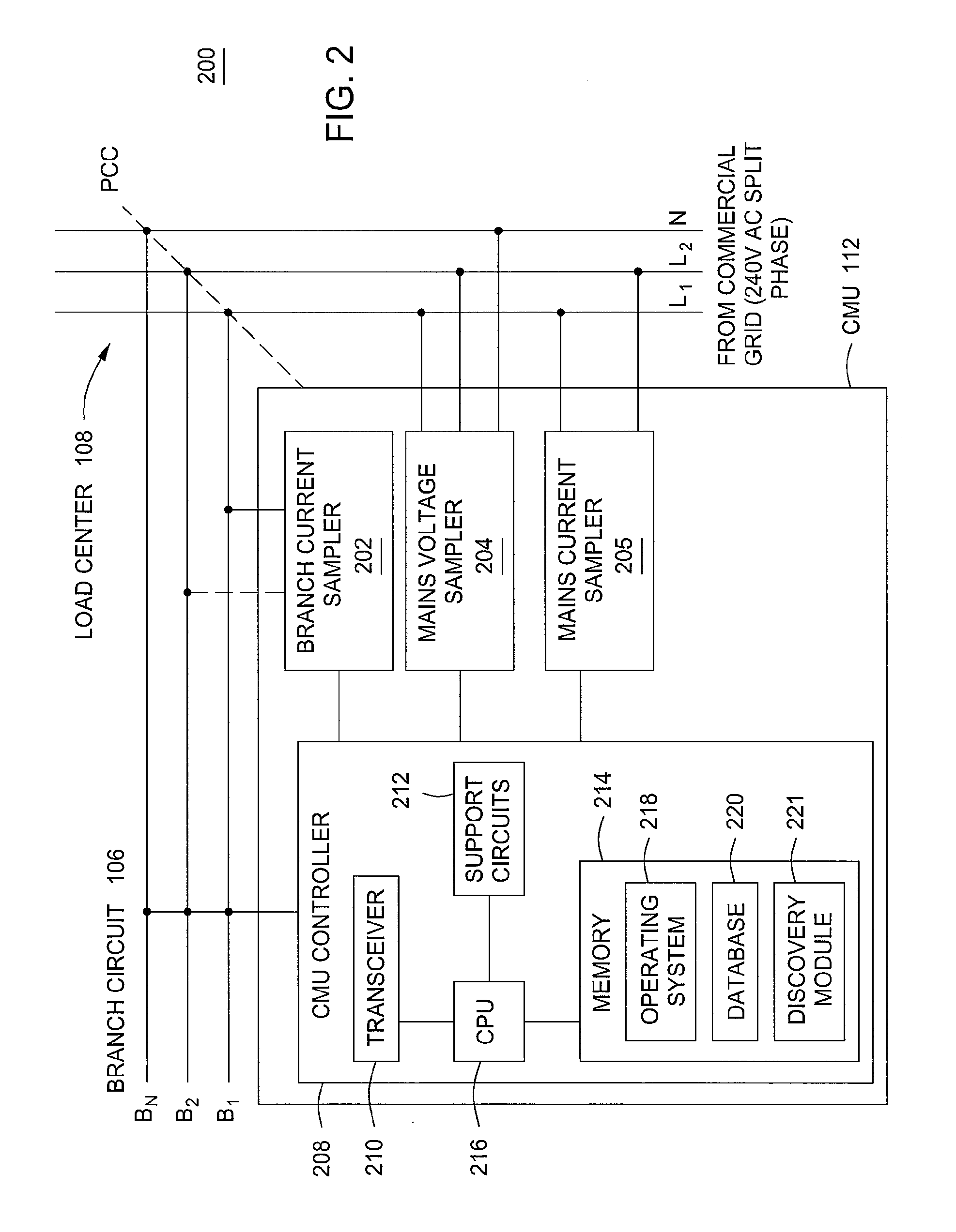
The present invention is about a way to characterize a circuit that is connected to an AC power line. It involves using a special device called a consumption measurement unit (CMU) that can measure the current and voltage on the power line. The CMU can create a signature for each phase of the power line based on the current and voltage samples it collects. By analyzing these signatures, the CMU can determine important information about the circuit, such as its type and voltage characteristics. This invention helps to better understand and control the performance of circuits that are connected to AC power lines.

Problems solved by technology

Due to the high cost of installation, solar panels were not an economical choice for generating power unless no other power options were available.
However, the worldwide growth of energy demand is leading to a durable increase in energy cost.
In addition, it is now well established that the fossil energy reserves currently being used to generate electricity are rapidly being depleted.
Proper installation of the data acquisition equipment is critical to provide accurate monitoring of the electrical data; improperly connected data acquisition equipment could result in invalid data and therefore present a potential safety hazard.

Method used


Image

  • Method and apparatus for characterizing a circuit coupled to an AC line
  • Method and apparatus for characterizing a circuit coupled to an AC line
  • Method and apparatus for characterizing a circuit coupled to an AC line

Examples


Embodiment Construction

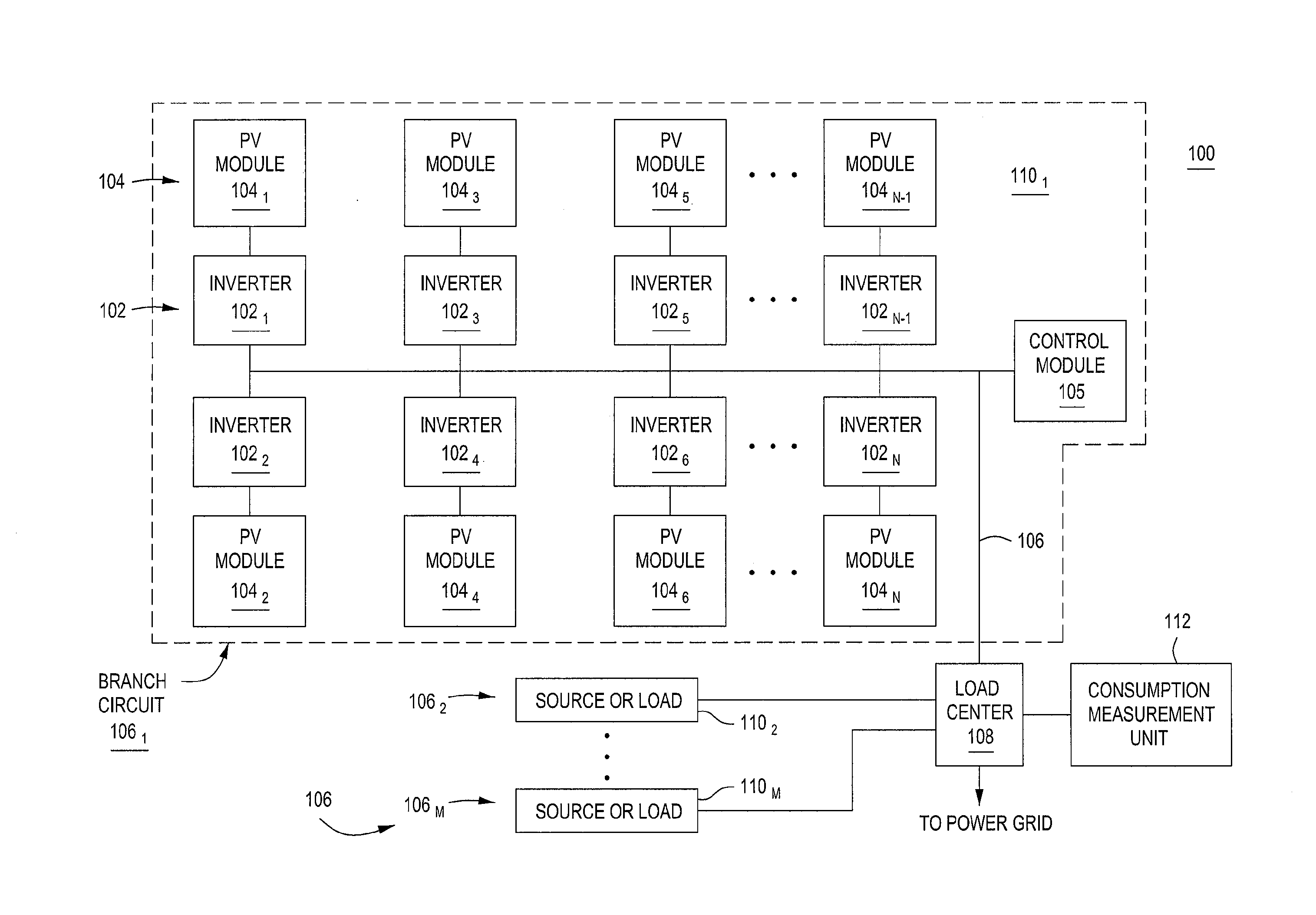
[0017]FIG. 1 is a block diagram of a power user's system 100 in accordance with one or more embodiments of the present invention. This diagram only portrays one variation of the myriad of possible system configurations. The present invention can function in a variety of distributed power generation environments and systems.

[0018]The system 100 comprises a plurality of branch circuits 1061, 1062 . . . 106m, collectively referred to as branch circuits 106, coupled to a load center 108. The load center 108 houses connections between incoming power lines from a commercial power grid distribution system and the branch circuits 106. Each branch circuit 1061, 1062 . . . 106m comprises a current source (e.g., a generator) or a load (e.g., an electrical appliance) 1101, 1102 . . . 110m.

[0019]In some embodiments, a branch circuit 1061 comprises a solar distributed generator (DG) acting as a source. The solar DG comprises a plurality of inverters 1021, 1022 . . . 102n, collectively referred to...


PUM


Abstract

A method and apparatus for characterizing a circuit coupled to an AC line. The apparatus comprises a consumption measurement unit (CMU), adapted for coupling, independent of voltage and current polarity, to the AC line and the circuit. The CMU comprises a discovery module adapted for (i) generating a circuit current signature based on current samples representative of current on a phase of the circuit, (ii) generating at least one AC line current signature based on AC line current samples representative of current on each phase of the AC line, and (iii) determining, based on the circuit current signature, the at least one AC line current signature, and at least one of a source profile or a load profile, at least one of a type or a voltage characteristic for the circuit.

Description

CROSS-REFERENCE TO RELATED APPLICATIONS[0001]This application claims benefit of U.S. provisional patent application Ser. No. 61 / 205,589, filed Jan. 21, 2009, which is herein incorporated in its entirety by reference.BACKGROUND OF THE INVENTION[0002]1. Field of the Invention[0003]Embodiments of the present disclosure generally relate to power systems and, more particularly, to a method and apparatus for characterizing a circuit coupled to an AC line.[0004]2. Description of the Related Art[0005]Solar panels have historically been deployed in mostly remote applications, such as remote cabins in the wilderness or satellites, where commercial power was not available. Due to the high cost of installation, solar panels were not an economical choice for generating power unless no other power options were available. However, the worldwide growth of energy demand is leading to a durable increase in energy cost. In addition, it is now well established that the fossil energy reserves currently ...

Claims


Application Information

Patent Timeline
Patent Type & Authority Applications(United States)
IPC IPC(8): H02J3/00
CPCG01R19/2513H02J3/383H02J3/382Y02E10/563Y02E10/763H02J3/386H02J2300/28H02J2300/20H02J2300/24H02J3/381Y02E10/56Y02E10/76H02J3/44
Inventor FORNAGE, MARTINDARGATZ, MARV
Owner ENPHASE ENERGY
Learn More