Knee Probe Having Reduced Thickness Section for Control of Scrub Motion

a scrub motion and thickness section technology, applied in the field of vertical probes, can solve the problems of increasing increasing the difficulty of tuning the scrub motion irrespective, and the difficulty of buckling beam probe assembly with ever decreasing scale, so as to improve the control of scrub motion and reduce the length of the scrub

Active Publication Date: 2010-07-22
MICRO PROBE
View PDF100 Cites 18 Cited by
  • Summary
  • Abstract
  • Description
  • Claims
  • Application Information

AI Technical Summary

Benefits of technology

[0018]Embodiments of the invention provide numerous advantages. The use of a probe having an “overshoot” knee as described above and in more detail below generally tends to increase the scrub motion compared to knee probes which do not “overshoot” the probe axis. In preferred embodiments, the invention makes use of multilayer probes, which facilitates the fabrication of probes having narrow “skates” on the probe tips. Such skates advantageously decouple the contact width (which should be small to increase contact for per unit area) from the probe width (which should be large enough to prevent motion in directions other than in the intended deflection plane). Multi-layer probes also allow the skate layers to be made of a suitable tip contact material, while the remaining layers are not constrained to be suitable tip contact materials. Dual-skate probe tips can be employed to probe contact pads having dimples at their centers (e.g., as provided by plating techniques for forming contact pads). In this case, the skates advantageously avoid the dimple, thereby avoiding issues relating to degraded electrical contact and increased mechanical stress on the probe tip that can arise when probing is performed directly at dimple locations.
[0020]Such reduction in scrub length can be provided according to the present invention by modifying the probe shape. More specifically, the probe knee section includes a reduced thickness section to alter the mechanical behavior of the probe when contact is made. Providing a reduced thickness section of the probe makes it easier to deflect the probe vertically when contact is made. This increased ease of vertical deflection tends to reduce the horizontal contact force component responsible for the scrub motion, thereby decreasing scrub length. Here “thickness” is the probe thickness in the deflection plane of the probe (i.e., the plane in which the probe knee lies).
[0022]Although reduction of scrub length for negative tip offset probes is one application of the invention, the invention is also applicable to probes having no tip offset and to positive tip offset probes. In general, embodiments of the present invention can provide improved control of scrub motion (e.g., by varying details of the reduced thickness section such as location, amount of thickness reduction, etc.), especially in combination with other probe parameters affecting scrub motion.

Problems solved by technology

As size and pitch of test contacts decrease, it becomes increasingly difficult to tune the scrub motion irrespective of friction influences in the tip / contact interface.
It is not acceptable to damage the low-K dielectric during probing operations either.
This makes the buckling beam probe's assembly increasingly challenging with ever decreasing scale.
This increased current density also raises issues which have not come up before in connection with large probes on large pads.
Breaking these micro-welds as the probe is removed from the contact pad can lead to degradation of the probe tip (e.g., by accumulation of non-conductive material), thereby reducing probe reliability and / or lifetime.
It is well known that electrical contact between the probe and the contact pad can be hampered by the presence of non-conductive material on the pad and / or the probe (e.g., a thin oxide film).
As circuit manufacturing technology continues to evolve to smaller critical dimensions, new practical issues relating to probing tend to arise which are not fully addressed by prior art approaches.
For example, the decreasing size of contact pads as critical dimensions are reduced leads to increasingly demanding requirements on the ability to precisely control the probe scrub motion.
Excessive scrub motion can cause loss of electrical contact, if the probe moves off the contact pad.

Method used


Image

  • Knee Probe Having Reduced Thickness Section for Control of Scrub Motion
  • Knee Probe Having Reduced Thickness Section for Control of Scrub Motion
  • Knee Probe Having Reduced Thickness Section for Control of Scrub Motion

Examples


Embodiment Construction

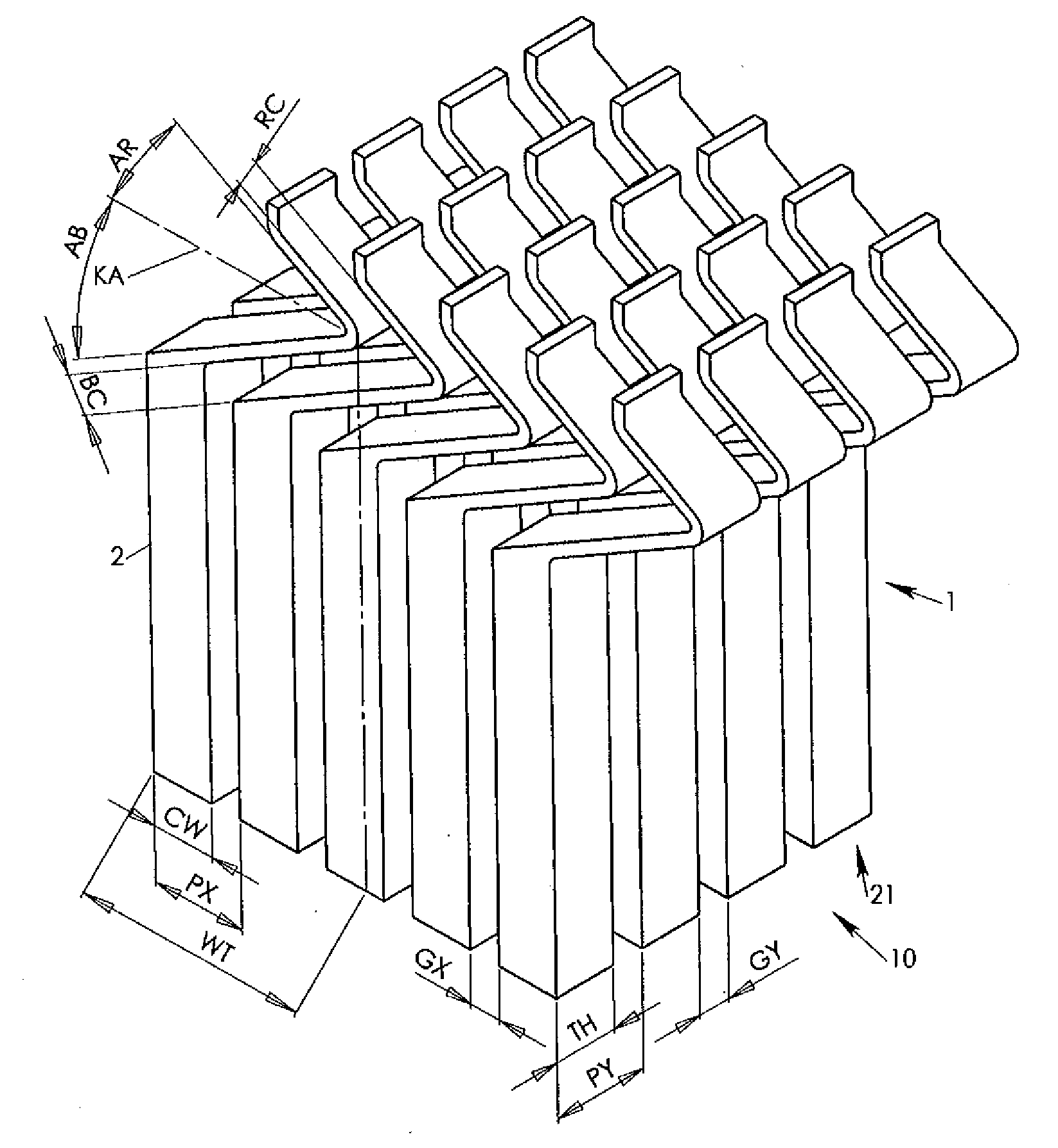
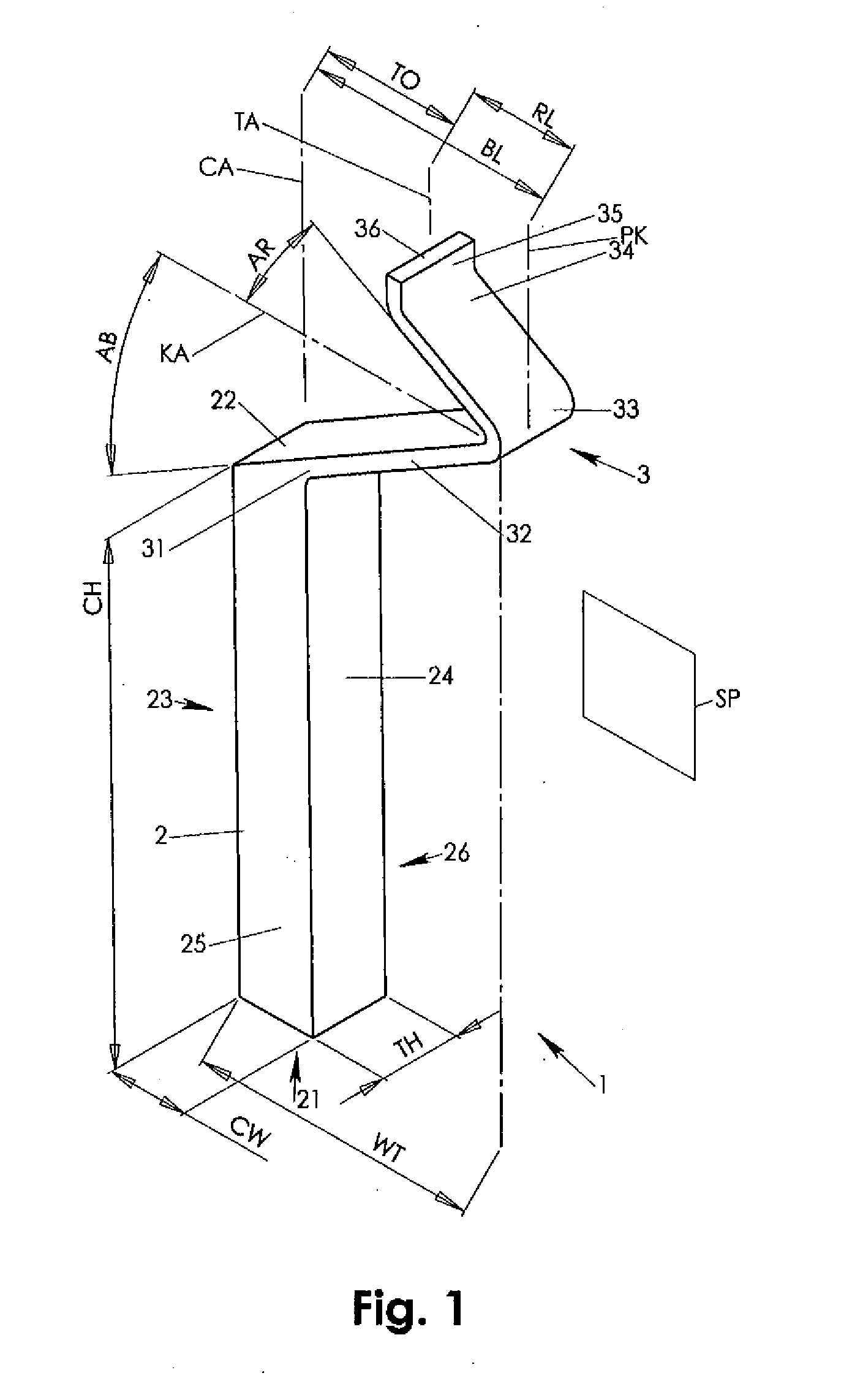
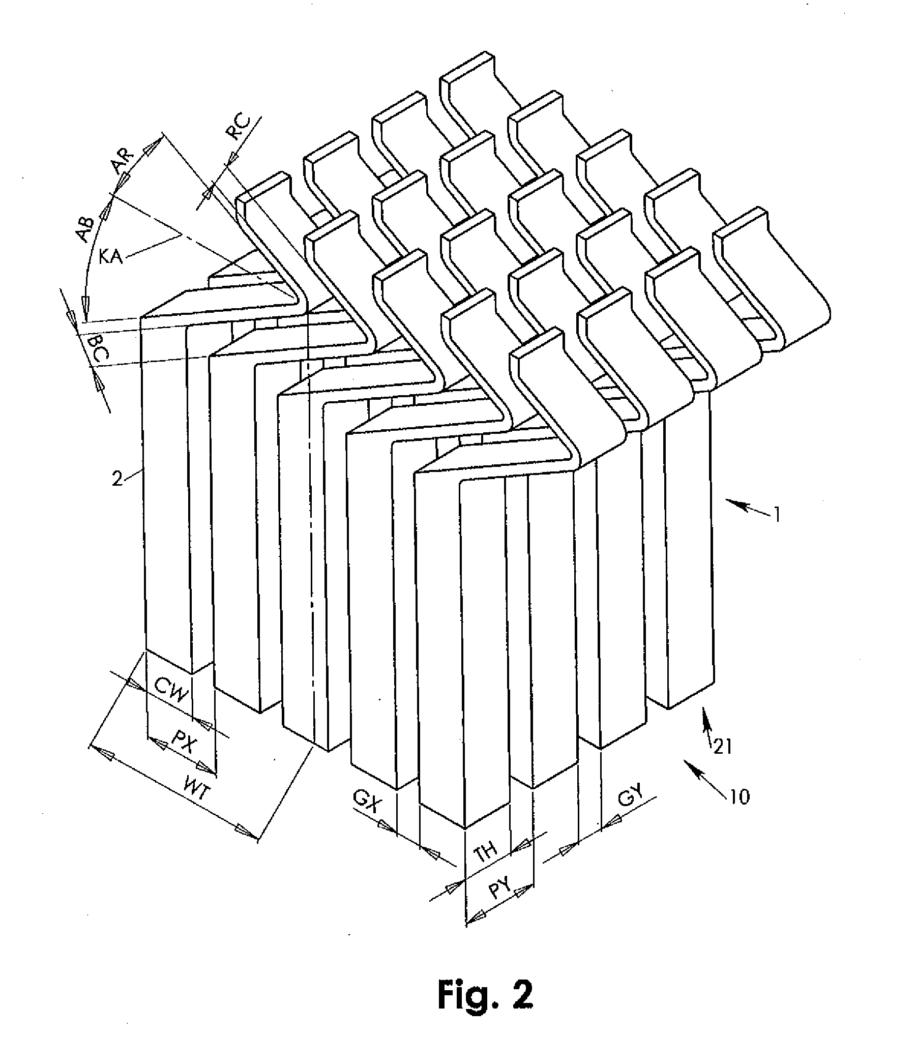
[0014]A preferably vertically assembled probe features a substantially rigid columnar structure and a connected suspension knee. The probe is held in assembly via its columnar structure. The suspension knee has a base arm laterally connecting at and propagating away from a connect end of the columnar structure. The base arm extends up to a lateral knee extension where a reverse arm continues from the base arm back in direction towards a central axis of the columnar structure. The reverse arm terminates in a contact tip in a tip offset to the column axis that is smaller than the lateral knee extension. During application of a contacting force onto the contact tip, a first deflection of the base arm and a second deflection of the reverse arm counter act in conjunction with base and reverse arms structural configuration. As a result, scrub motion may be well defined in direction and magnitude without need for additional guidance of the deflecting probe structure.

[0015]The entire probe ...


PUM


Abstract

An improved knee probe for probing electrical devices and circuits is provided. The improved knee probe has a reduced thickness section to alter the mechanical behavior of the probe when contact is made. The reduced thickness section of the probe makes it easier to deflect the probe vertically when contact is made. This increased ease of vertical deflection tends to reduce the horizontal contact force component responsible for the scrub motion, thereby decreasing scrub length. Here “thickness” is the probe thickness in the deflection plane of the probe (i.e., the plane in which the probe knee lies). The reduced thickness probe section provides increased design flexibility for controlling scrub motion, especially in combination with other probe parameters affecting the scrub motion.

Description

CROSS REFERENCE TO RELATED APPLICATIONS[0001]This application is a continuation application of U.S. patent application Ser. No. 11 / 521,944, entitled “Knee Probe Having Reduced Thickness Section for Control of Scrub Motion”, to January Kister, filed Sep. 14, 2006, which is a continuation-in-part application of U.S. patent application Ser. No. 11 / 450,977, entitled “Knee Probe Having Increased Scrub Motion”, to January Kister, filed on Jun. 9, 2006, which is a continuation-in-part application of U.S. patent application Ser. No. 10 / 850,921 (now U.S. Pat. No. 7,148,709), entitled “Freely Deflecting Knee Probe with Controlled Scrub Motion”, to January Kister, filed May 21, 2004, and all of the specifications and claims thereof are incorporated herein by reference.BACKGROUND OF THE INVENTION[0002]1. Field of the Invention[0003]The present invention relates to probes for testing electronic circuitry. Particularly, the present invention relates to vertical probes having a rigid columnar stru...

Claims


Application Information

Patent Timeline
Patent Type & Authority Applications(United States)
IPC IPC(8): G01R1/06
CPCG01R1/06733G01R1/07357
Inventor KISTER, JANUARY
Owner MICRO PROBE
Why Eureka
Try Eureka