Control and coordination of transcranial magnetic stimulation electromagnets for modulation of deep brain targets

a transcranial magnetic stimulation and electromagnet technology, applied in magnetotherapy, magnetotherapy using coils/electromagnets, magnetotherapy, etc., can solve the problems of inability to meet the complexity of the nervous system, ineffective electrical efficiency, and limited ability of the current available rtms pulse generator unit, so as to avoid over-stimulating structures

Inactive Publication Date: 2010-07-22
CERVEL NEUROTECH
View PDF99 Cites 116 Cited by
  • Summary
  • Abstract
  • Description
  • Claims
  • Application Information

AI Technical Summary

Benefits of technology

[0035]As used herein, an attractor magnet is typically a secondary magnet positioned separately from the primary TMS magnet(s) whose magnetic field the attractor magnet is configured to modify. An attractor magnet may be isolated from the primary TMS electromagnet(s) whose field it is configured to modify. In particular the attractor magnet may be physically isolated, meaning that it may not be directly connected to a primary electromagnet. In some variations, the attractor magnet is separately maneuverable from the primary electromagnet, though it may be connected to the same gantry, framework, etc. as the primary electromagnet(s). For example, an attractor magnet may be positioned opposite from a primary TMS magnet and configured to direct, focus, or otherwise enhance the electromagnetic field emitted by the TMS magnet, which may aid in delivering deeper, more effective Transcranial Magnetic Stimulation (TMS). Typically, TMS involves uses a large electromagnet placed near the side of the patient's head to provide electromagnetic simulation. For the purposes of this document, the primary TMS (e.g., large) electromagnet is herein referred to as a “primary magnet,”“primary electromagnet” or a “main electromagnet”. The secondary magnets described herein, which may be located separately from the primary magnet but can be activated simultaneously or synchronously (in the case of active secondary magnets) with the primary magnet. For example, one or more attractor magnets may be located on the side of a patient's head opposite from the primary TMS magnet(s), or in the mouth or nasal cavity, and may act as active sink for the magnetic field from the magnet to help focus the field.
[0037]Because the magnetic fields produced by TMS magnets have complex, 3-dimensional field strength profiles, the term “opposite” polarity may be relative. Consequently, the primary TMS magnet and an attractor magnet do not need to be positioned at 180 degrees with respect to one another. For example, a primary magnet and an attractor magnet may face 90 degrees relative to one another, and still produce the attractor effect as herein described. In some variations the attractor magnet may be moved relative to the TMS magnet (or vice versa). In general, the attractor magnet may be positioned so that the effect of the attractor magnet on the magnetic field of the TMS magnet is predictable.
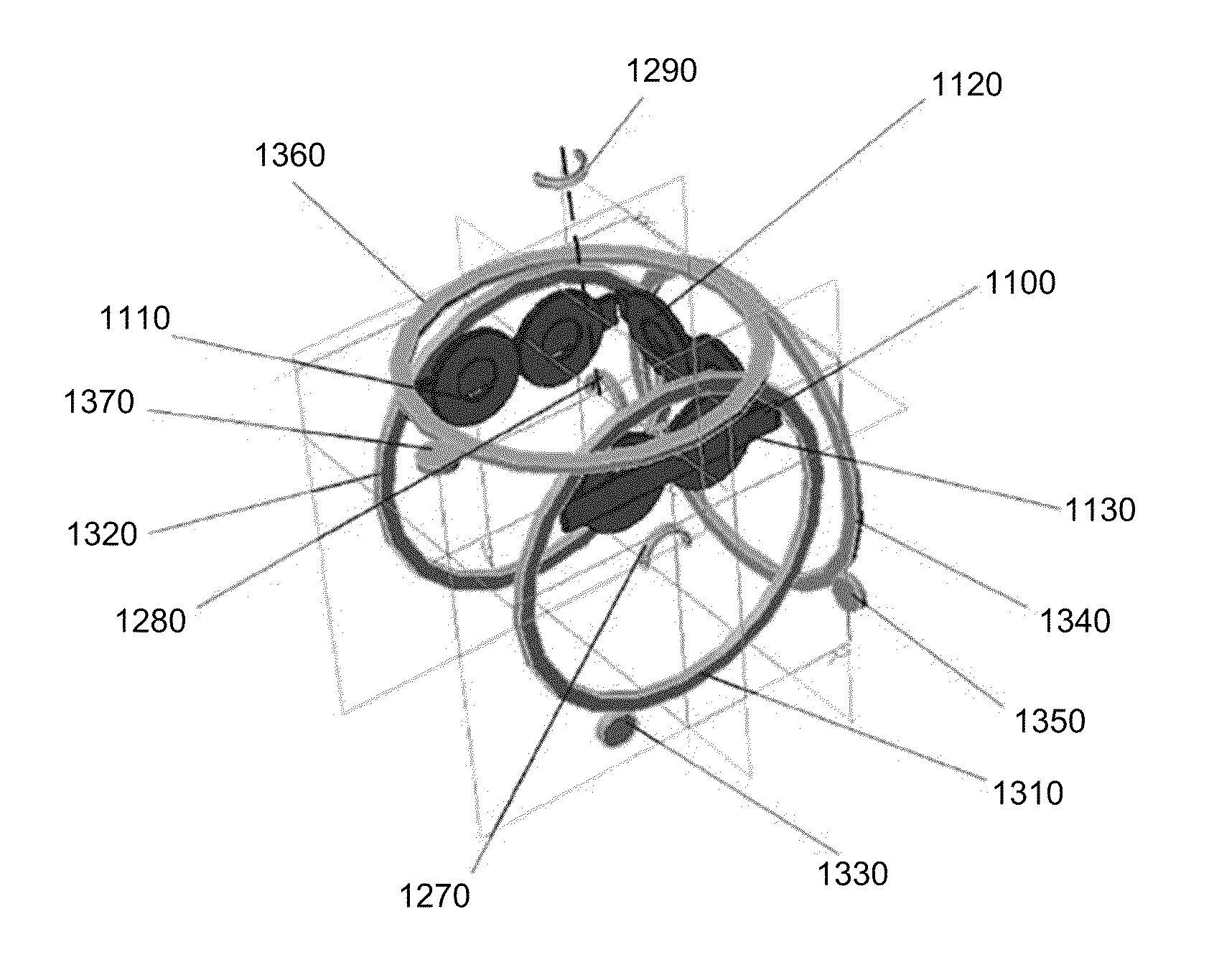
[0041]Part III describes systems, devices and method for Transcranial Magnetic Stimulation (TMS) in which the TMS electromagnets are configured to move in a pitch motion, a roll motion, a yaw motion, or two or three of those in combination. Moving the TMS electromagnet(s) in pitch, roll and / or yaw during treatment may avoid over-stimulating structures and causing undesirable side effects such as seizures.
[0061]In some variations, the distance between the TMS electromagnet and the subject is adjusted by moving both the TMS electromagnets around the gantry and by moving the gantry around the patient's head. For example, when a patient's head is positioned in the center of an oval gantry, moving the TMS electromagnet closer to the short axis of the oval will shorten the distance between the TMS electromagnet and the center of the oval; conversely, moving the TMS electromagnet closer to the long axis increases the distance to the center of the oval. Thus, moving the TMS electrode (which may be part of a TMS actuator module) around the gantry changes the radial position relative to the center of the gantry and therefore the patient, while moving the entire gantry may position the TMS electrode relative to the region of the patient's head. The combined motions of the gantry rotation and rotation of the TMS actuator module around the gantry, may be used to control the distance between the subject and the TMS electromagnet. In this embodiment, the TMS actuator module typically includes one or more TMS electromagnets and at least one gantry / magnet actuator configured to move the TMS electromagnet(s) around the gantry.
[0087]Although patient feedback / control during the TMS therapy is typically experiential, or based on the reported experience of the patient, it may also (or alternatively) be controlled by one or more involuntary, unconscious, and / or physiological patient responses. For example, successful TMS treatment may cause an involuntary or physiological response that is not recognized by the patient, such as increase or decrease in heart rate, blood pressure, respiratory rate, etc. This type of ‘involuntary’ patient feedback may also be detected by the system, and may be used to modify the treatment. In some variations, the system may prevent false or erroneous reporting of conscious or volitional feedback by requiring both unconscious and conscious feedback. For example, if treating pain, the system may allow the patient to continue to adjust one or more parameter during TMS treatment (patient control feedback), as long as an ‘unconscious’ patient feedback does not indicate successful treatment (e.g., change in heart rate, blood pressure, etc., indicating alleviation in pain). Alternatively, the unconscious or involuntary patient feedback may be used to select the parameter controlled by the patient or the magnitude of the patient control.
[0092]Also described herein are patient-configurable Transcranial Magnetic Stimulation (TMS) methods that allows a patient to dynamically modify the TMS while a TMS procedure is being performed, the method comprising: positioning a plurality of TMS electromagnets to apply electromagnetic energy to a deep brain target site; applying TMS to the target site at a magnetic field intensity and a stimulation frequency; enabling the patient to change one or more of the position of the TMS electromagnet, the intensity of the TMS stimulation, or the frequency of the TMS stimulation based the patient's experience of the applied TMS stimulation; and applying Transcranial Magnetic Stimulation to the patient at the changed position of the TMS electromagnet, intensity of the TMS stimulation, or frequency of TMS stimulation.

Problems solved by technology

However, presently available rTMS pulse generator units are limited in their ability to provide the optimal signal to such a coil array.
However, the complexity of the polyphasic waveform, meeting the complexity of the nervous system frequently yields inconsistent results.
Electrically inefficient, these machines are not capable of sustained, rapid pulse trains.
The prior art does not provide any means for coordinating pulse phase, timing polarity or strength between more than one coil.
Deep brain modulation cannot be accomplished by simply turning up the power of the stimulating electromagnet, because the intervening tissue, for example superficial cortex, will be over-stimulated, causing undesired side effects such as seizures.
A circular orbit is inefficient from the energy delivery standpoint: magnetic field strength falls off rapidly as it leaves the face of a coil.
US 2003 / 0050527) are overly complex and expensive, and would require complicated control systems in order to maintain appropriate spacing between the electromagnet and the subject's head.
Deep brain targets are of particular interest for TMS, but practical deep-brain TMS has been difficult to achieved, because stimulation at depth must be performed without over-stimulating superficial tissues.
This type of control does not allow functional feedback, and may be less accurate and also less effective than a system that would somehow directly confirm adequate stimulation of the appropriate brain region necessary for achieving therapeutic effect.
Fox and Lancaster, U.S. Pat. No. 7,087,008 teach a robotic system for positioning TMS coils involving PET scanning to locate the target, but the system does not use direct patient-reported feedback.
While the above-described approaches can be useful, they are not applicable in ambulatory settings where the vast numbers of patients will be treated.
Although patient-reported feedback has been applied with some success in other treatment types, such as implantable electrode stimulation, it has not been applied to TMS therapies.

Method used


Image

  • Control and coordination of transcranial magnetic stimulation electromagnets for modulation of deep brain targets
  • Control and coordination of transcranial magnetic stimulation electromagnets for modulation of deep brain targets
  • Control and coordination of transcranial magnetic stimulation electromagnets for modulation of deep brain targets

Examples


Embodiment Construction

Part I: Monophasic Multi-Coil Arrays for Transcranial Magnetic Stimulation

[0138]Described below is the use of one or more (e.g., an array) of TMS electromagnets to stimulate the brain treatment of hypertension.

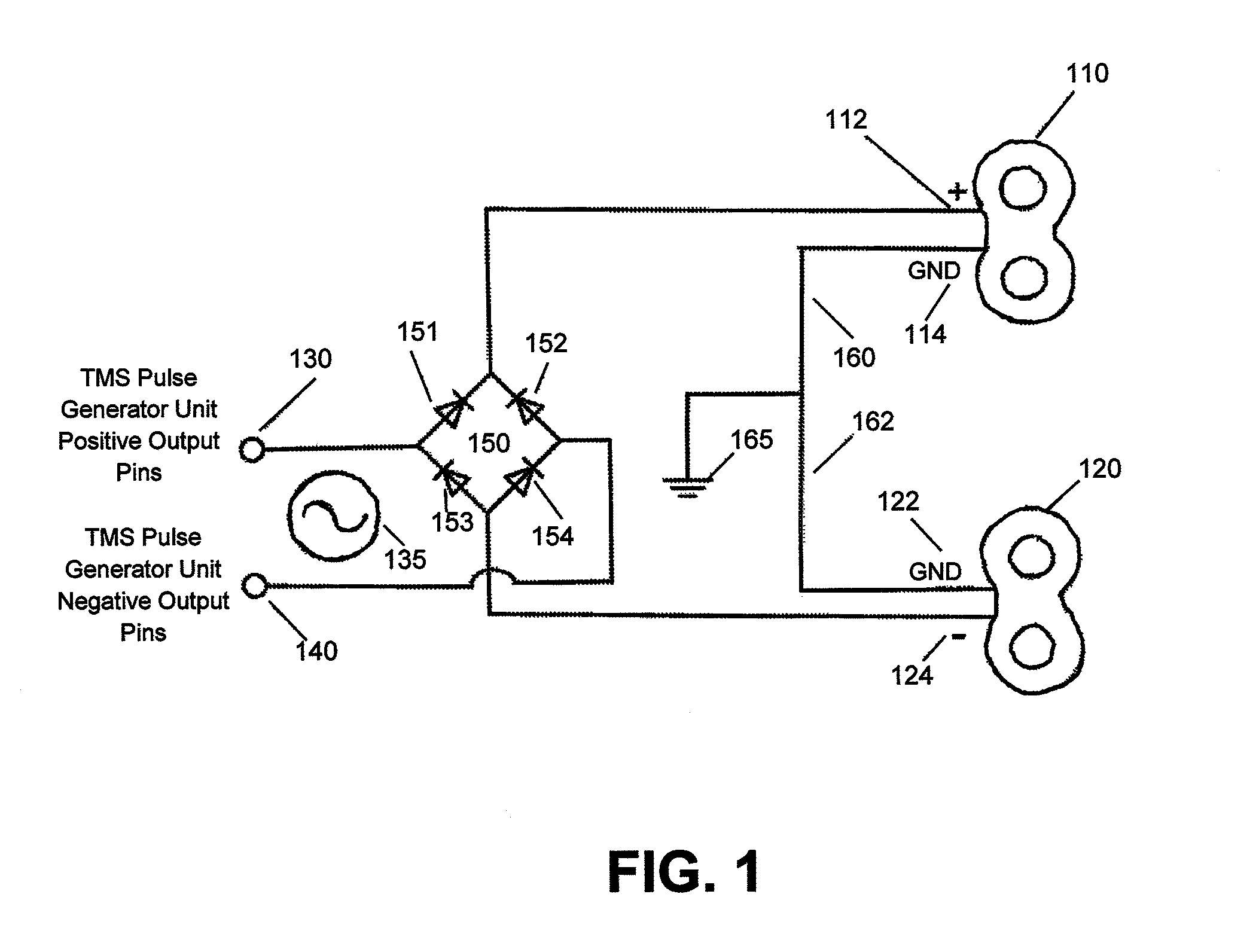
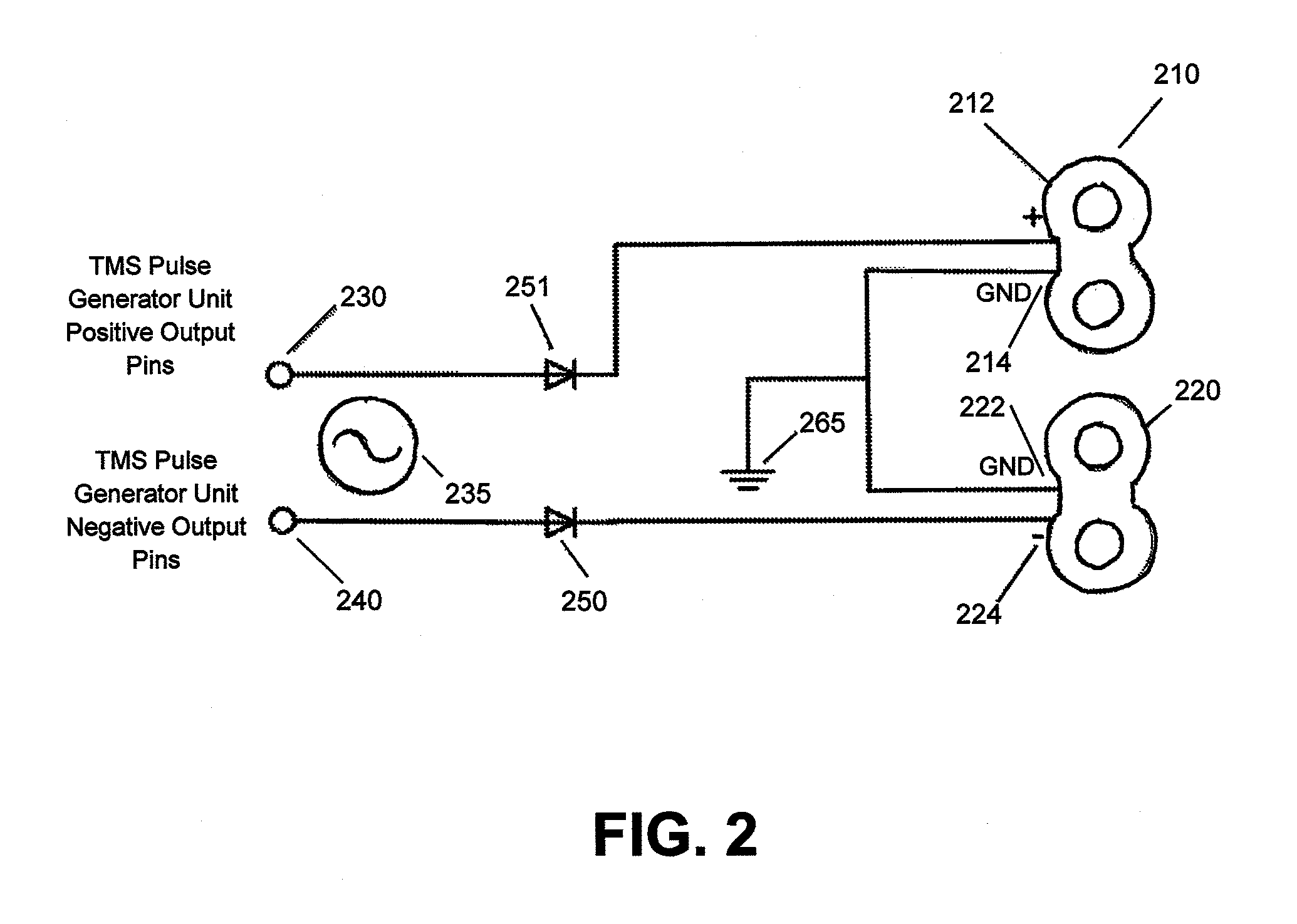
[0139]FIG. 1 shows a circuit diagram of a full-wave rectifier circuit applied to a two-coil array. In this particular embodiment, the two coils in the array, coil 110 and coil 120 are double coils, for example 70 mm double coil manufactured by Magstim Ltd. (Wales, UK). In such a double coil, two separate concentric windings are wrapped in opposite directions with a crossover between the two portions, placed such that the positive and the negative going leads to the two coil portions run electrical current in the same direction where the two portions are adjacent to one another, creating the greatest magnetic field induction under the center. Positive electrical pole 130 and negative electrical pole 140 have a pulsatile polyphasic alternating current 135 between them, and repre...


PUM


Abstract

Described herein are devices and method for control and coordination of TMS electromagnets for modulation of deep brain targets. For example, described herein are methods and devices for stimulating neural structures within the brain using multi-coil arrays. Also described herein are devices and methods that relate generally to the focusing of magnetic fields generated by electromagnets used for Transcranial Magnetic Stimulation. Devices and methods relating generally to the focusing of magnetic fields generated by electromagnets used for Transcranial Magnetic Stimulation are also described, as well as devices and methods that relate generally to moving and positioning electromagnets generating magnetic fields used for Transcranial Magnetic Stimulation. Finally, also described are devices and methods that relate generally to control of moving, positioning, and activating electromagnets generating magnetic fields used for Transcranial Magnetic Stimulation.

Description

CROSS REFERENCE TO RELATED APPLICATIONS[0001]This application claims priority as a continuation-in-part of U.S. patent application Ser. No. 12 / 185,544, titled “MONOPHASIC MULTI-COIL ARRAYS FOR TRANCRANIAL MAGNETIC STIMULATION,” filed on Aug. 4, 2008, which claims priority to U.S. Provisional Patent Application Ser. No. 60 / 954,018, titled “MONOPHASIC MULTI-COIL ARRAYS FOR TRANCRANIAL MAGNETIC STIMULATION” filed on Aug. 5, 2007. This application is also a continuation-in-part of PCT International Patent Application Serial No. PCT / US2008 / 075575, titled “FOCUSING MAGNETIC FIELDS WITH ATTRACTOR MAGNETS AND CONCENTRATOR DEVICES,” filed on Sep. 8, 2008 (published as WO 2009 / 033144), which claims priority to U.S. Provisional Patent Applications: No. 60 / 970,532, titled “FOCUSING MAGNETIC FIELDS WITH CONCENTRATION DEVICES,” filed on Sep. 7, 2007; No. 60 / 970,534, titled “FOCUSED MAGNETIC FIELDS USING ATTRACTOR MAGNETS,” filed on Sep. 7, 2007; and No. 60 / 975,177, titled “FOCUSING MAGNETIC FIELD...

Claims


Application Information

Patent Timeline
Patent Type & Authority Applications(United States)
IPC IPC(8): A61N2/02
CPCA61N2/02A61N2/004
Inventor SCHNEIDER, M. BRETMISHELEVICH, DAVID J.
Owner CERVEL NEUROTECH
Why Eureka
Try Eureka