
Asynchronous Scan Chain Circuit

a technology of asynchronous scan and chain circuit, applied in the field of integrated circuits test, can solve the problems of insufficient research in dft for asynchronous circuits, difficult test pattern generation for asynchronous circuits, unsatisfactory fault coverage, etc., and achieve the effect of high fault detection coverage and low power

Inactive Publication Date: 2010-07-22
NAT TAIWAN UNIV
View PDF9 Cites 21 Cited by
  • Summary
  • Abstract
  • Description
  • Claims
  • Application Information

AI Technical Summary

Benefits of technology

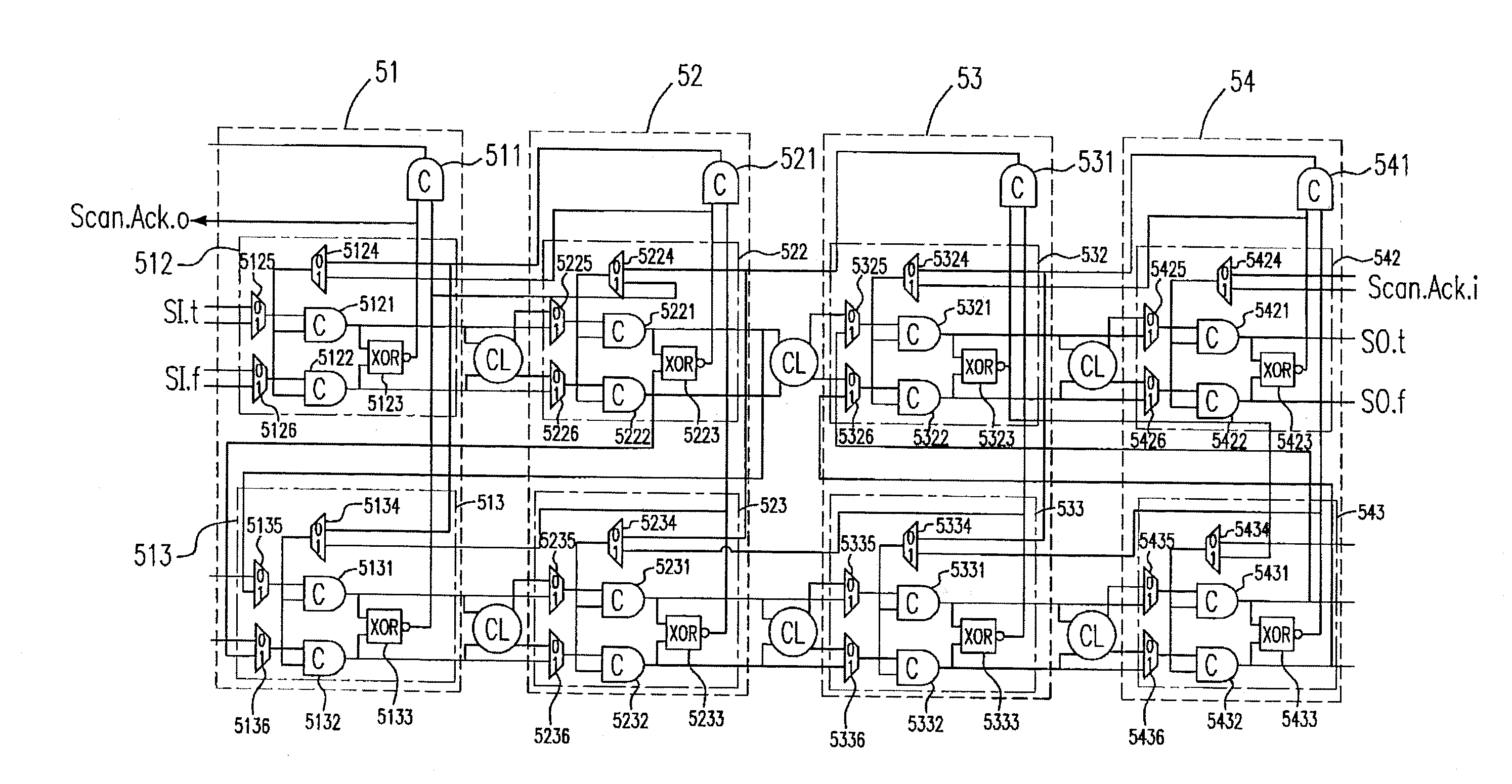
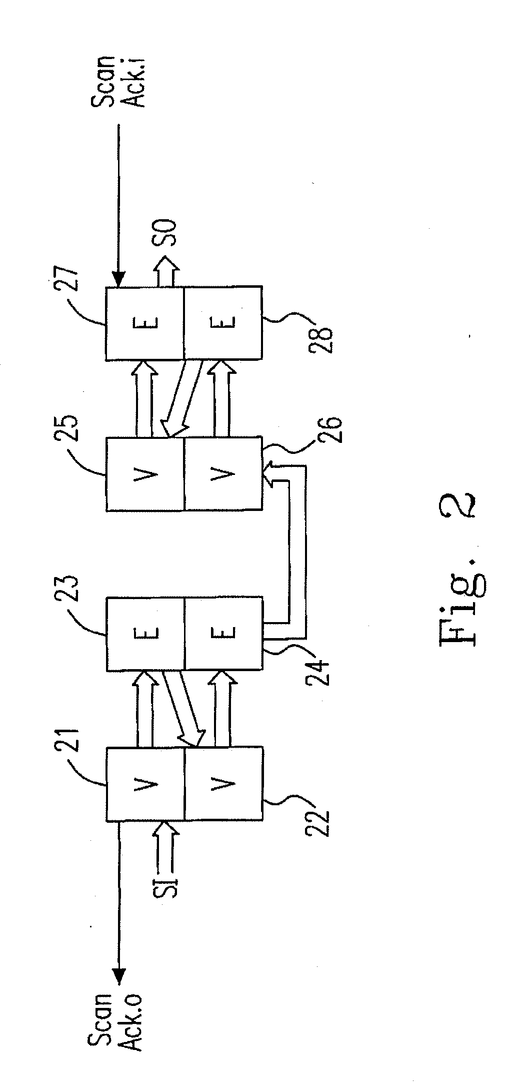
[0006]The present invention provides a dual-rail asynchronous scan chain circuit, controlling the scan chain input test pattern and outputting the test outcome according to the handshake protocol between each two of scan units. The asynchronous scan chain circuit does not require any clock in functional or scan mode so it is a truly asynchronous design for testability (DFT). Furthermore, the present invention not only consumes very low power and avoids the clock skew problems, but also achieves high fault detection coverage.

Problems solved by technology

Unfortunately, traditional design for testability (DFT), such as scan chains, is mainly for synchronous circuits with clocks.
Without DFT, test pattern generation for asynchronous circuits is very difficult and fault coverage is unsatisfactory.
So far, there is still insufficient research in DFT for asynchronous circuits.
Although the synchronous technology-based circuit plus some special automated instrument can be configured as an asynchronous circuit for test, the DFT of asynchronous circuits for thorough scan is still not mature.
According to the above drawback in the prior art, the applicant uses asynchronous handshaking circuit design to accomplish overall scan and reach high fault detection coverage rate without any clock control and affection in system operation.

Method used


Image

  • Asynchronous Scan Chain Circuit
  • Asynchronous Scan Chain Circuit
  • Asynchronous Scan Chain Circuit

Examples


Embodiment Construction

[0032]The present invention will now be described more specially with reference to the following embodiments. It is to be noted that the following descriptions of preferred embodiments of this invention are presented herein for the purposes of illustration and description only; it is not intended to be exhaustive or to be limited to the precise form disclosed.

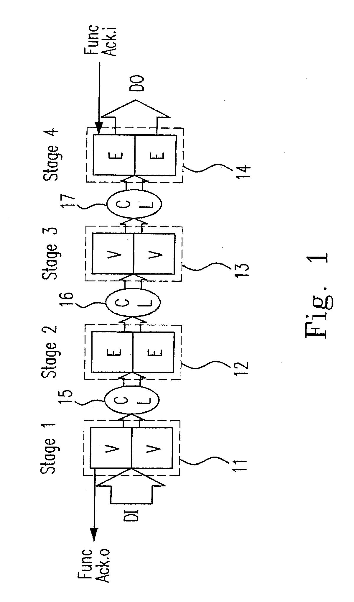
[0033]Please refer to FIG. 1, which is a block diagram showing the data flow of a dual-rail asynchronous pipeline circuit in functional mode. “DI” and “DO” are data inputs and outputs, respectively. “CL” stands for dual-rail combinational logic. The asynchronous pipeline circuit includes: a first stage 11, a second stage 12, a third stage 13, a fourth stage 14, a first combinational logic 15, a second combinational logic 16, a third combinational logic 17 and a fourth combinational logic 18. Each stage of the pipeline circuit consists of two latches. In functional mode, the odd stages latches (11,13) hold valid data, indicated ...


PUM


Abstract

Disclosed is a dual-rail asynchronous insensitive scan chain circuit designed for test. This scan chain does not require any clock even in scan mode, so it is truly an asynchronous design for testability. The normal function of the asynchronous scan chain can not be affected when removing any clock controls. The handshake protocols between two sequential elements used in the asynchronous scan chain become the scan chain transmission structure, rather than the timing control used in synchronous scan chain in the prior arts. Therefore, both in the function mode and scan mode, the scan chain always operates under the asynchronous condition. It not only can reach a complete test scanning, achieve high fault detection coverage and consume lower power, but also avoid the clock skew problem.

Description

FIELD OF THE INVENTION[0001]The present invention relates to integrated circuits test, and more particularly, to a dual-rail asynchronous insensitive scan chain circuit designed for test.BACKGROUND OF THE INVENTION[0002]As TFT technology is not yet mature, a thorough testing of TFT circuits is essential to make sure they are free of defects. Unfortunately, traditional design for testability (DFT), such as scan chains, is mainly for synchronous circuits with clocks. Without DFT, test pattern generation for asynchronous circuits is very difficult and fault coverage is unsatisfactory. So far, there is still insufficient research in DFT for asynchronous circuits.[0003]Although the synchronous technology-based circuit plus some special automated instrument can be configured as an asynchronous circuit for test, the DFT of asynchronous circuits for thorough scan is still not mature. Specially designed test pattern generators are needed to produce the useful test pattern. Moreover, external...

Claims


Application Information

Patent Timeline
IPC IPC(8): G01R31/3177G06F11/25
CPCG01R31/318541G01R31/318572
Inventor LI, CHIEN-MOCHENG, CHI-HSUAN
Owner NAT TAIWAN UNIV
Learn More