Electromagnetic Energy Scavenger Based on Moving Permanent Magnets

a technology of moving permanent magnets and energy scavengers, which is applied in the direction of microstructural devices, microstructured devices, dynamo-electric machines, etc., can solve the problems of real vibration sources showing a considerable amount of energy, the scaling down of batteries for powering these sensor nodes is subject to technological restrictions, and the loss of storage density

Inactive Publication Date: 2010-07-29
STICHTING IMEC NEDERLAND
View PDF10 Cites 47 Cited by
  • Summary
  • Abstract
  • Description
  • Claims
  • Application Information

AI Technical Summary

Benefits of technology

[0009]It is an object of embodiments of the present invention to provide good apparatus or methods for generating energy by electromagnetic means.

Problems solved by technology

The scaling down of batteries for powering these sensor nodes faces technological restrictions as well as a loss in storage density.
However, real vibration sources typically show a considerable amount of energy apart from the resonant frequency.
Again, the maximum displacement of the magnet relative to the coil is limited by the size and the structure of the generator.
The applicability of these systems is limited to the bandwidth of their mechanical resonance.
Miniaturized resonant systems can hardly be designed for frequencies lower than 50 Hz, as e.g. encountered in human body motion or long stroke machine operation.
This is due to the fact that the required mechanical parameters, i.e. high mass and low suspension stiffness, are difficult to obtain with the dimensions of miniaturized systems.
However, it is a disadvantage of the Spreeman system that there is a need for converting a linear motion into rotation of the pendulum.
Miniaturization, as required for use in wireless sensor nodes, is expected to be challenging because the mechanism requires a bearing which can hold relatively high moments.

Method used


Image

  • Electromagnetic Energy Scavenger Based on Moving Permanent Magnets
  • Electromagnetic Energy Scavenger Based on Moving Permanent Magnets
  • Electromagnetic Energy Scavenger Based on Moving Permanent Magnets

Examples


Embodiment Construction

[0054]The present invention will be described with respect to particular embodiments and with reference to certain drawings but the invention is not limited thereto. The drawings described are only schematic and are non-limiting. In the drawings, the size of some of the elements may be exaggerated and not drawn on scale for illustrative purposes. The dimensions and the relative dimensions do not correspond to actual reductions to practice of the invention.

[0055]Furthermore, the terms first, second, third and the like in the description and the claims, are used for distinguishing between similar elements and not necessarily for describing a sequential or chronological order. The terms are interchangeable under appropriate circumstances and the embodiments of the invention can operate in other sequences than described or illustrated herein.

[0056]Moreover, the terms top, bottom, over, under and the like in the description and the claims are used for descriptive purposes and not necessa...


PUM


Abstract

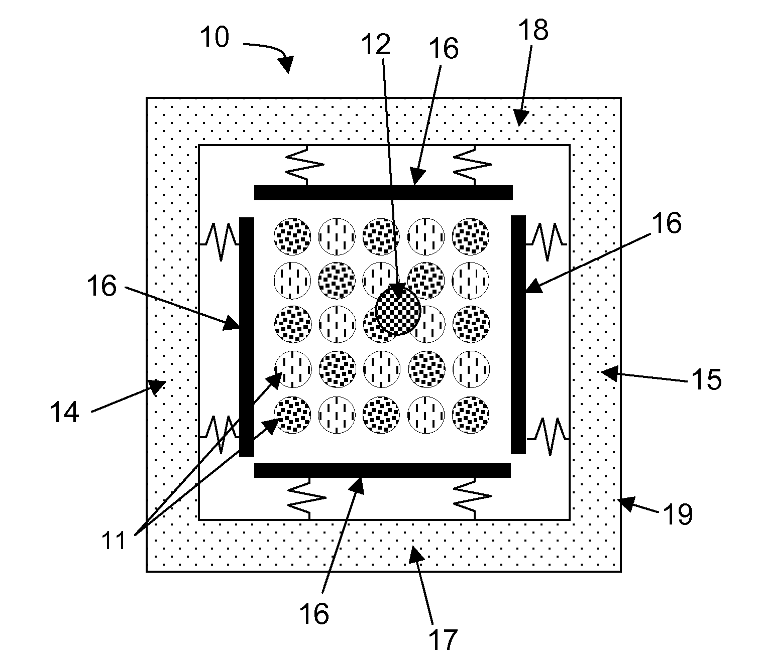
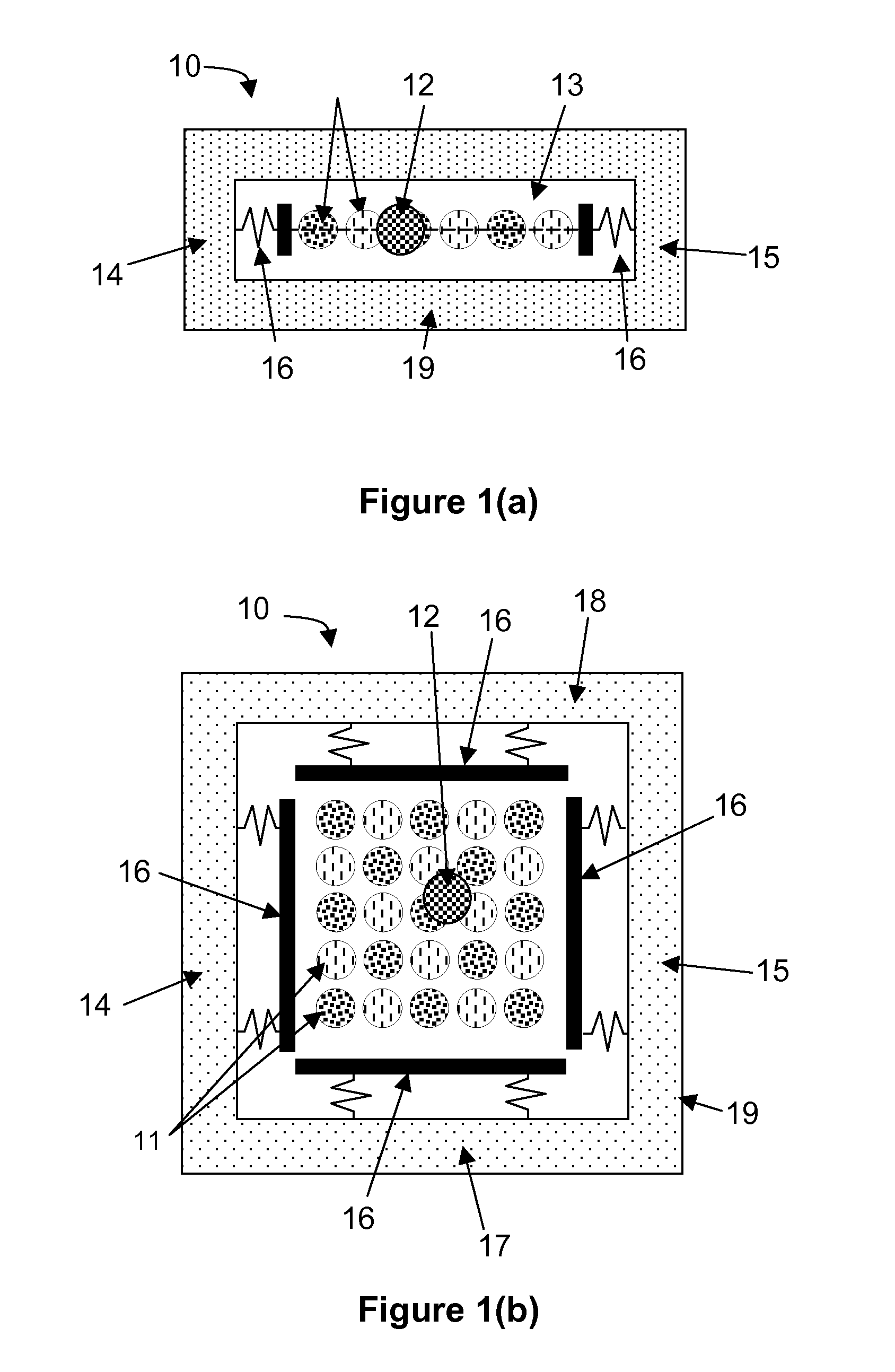
An electromagnetic energy scavenger (10) for converting kinetic energy into electrical energy comprises at least one permanent magnet (12) and one or more coils (11) lying in a coil plane, the one or more coils being electrically interconnected for delivery of electrical energy. Upon mechanical movement of the energy scavenger (10), the at least one permanent magnet (12) is freely movable relative to the coils (11) in a plane parallel to the coil plane, thus generating an electrical field in at least one coil (11).

Description

TECHNICAL FIELD OF THE INVENTION[0001]This invention generally relates to a method for generating energy by electromagnetic means and to a device or energy scavenger for generating energy by electromagnetic means. The electromagnetic energy scavengers of the present invention may be miniaturized based on microfabrication techniques. The energy scavengers may for example be used in wireless systems such as wireless autonomous transducer systems, e.g. for powering wireless autonomous sensors.BACKGROUND[0002]Future wireless sensor networks will comprise sensor nodes which occupy a volume of typically a few cm3. The scaling down of batteries for powering these sensor nodes faces technological restrictions as well as a loss in storage density. For this reason a worldwide effort is ongoing to replace batteries with more efficient, miniaturized power sources. Energy scavengers based on the recuperation of wasted ambient energy are a possible alternative to batteries. Several scavenger conc...

Claims


Application Information

Patent Timeline
Patent Type & Authority Applications(United States)
IPC IPC(8): F03G7/08H02K35/02
CPCB81B3/0021H02K2201/18H02K35/02H02K7/1876
Inventor HOHLFELD, DENNISVULLERS, RUUD
Owner STICHTING IMEC NEDERLAND
Why Eureka
Try Eureka