
Method of continuous inkjet printing

a technology of inkjet printing and continuous ink, which is applied in the direction of liquid handling, volume metering, instruments, etc., can solve the problems of difficult array manufacturing, reduce thermal degradation effect of dispersed material, improve uv curable monomer, and reduce thermal degradation

Inactive Publication Date: 2010-07-29
EASTMAN KODAK CO
View PDF5 Cites 3 Cited by
  • Summary
  • Abstract
  • Description
  • Claims
  • Application Information

AI Technical Summary

Benefits of technology

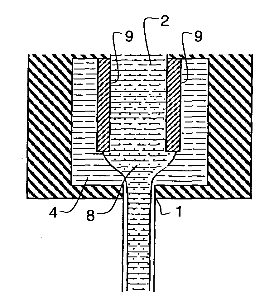
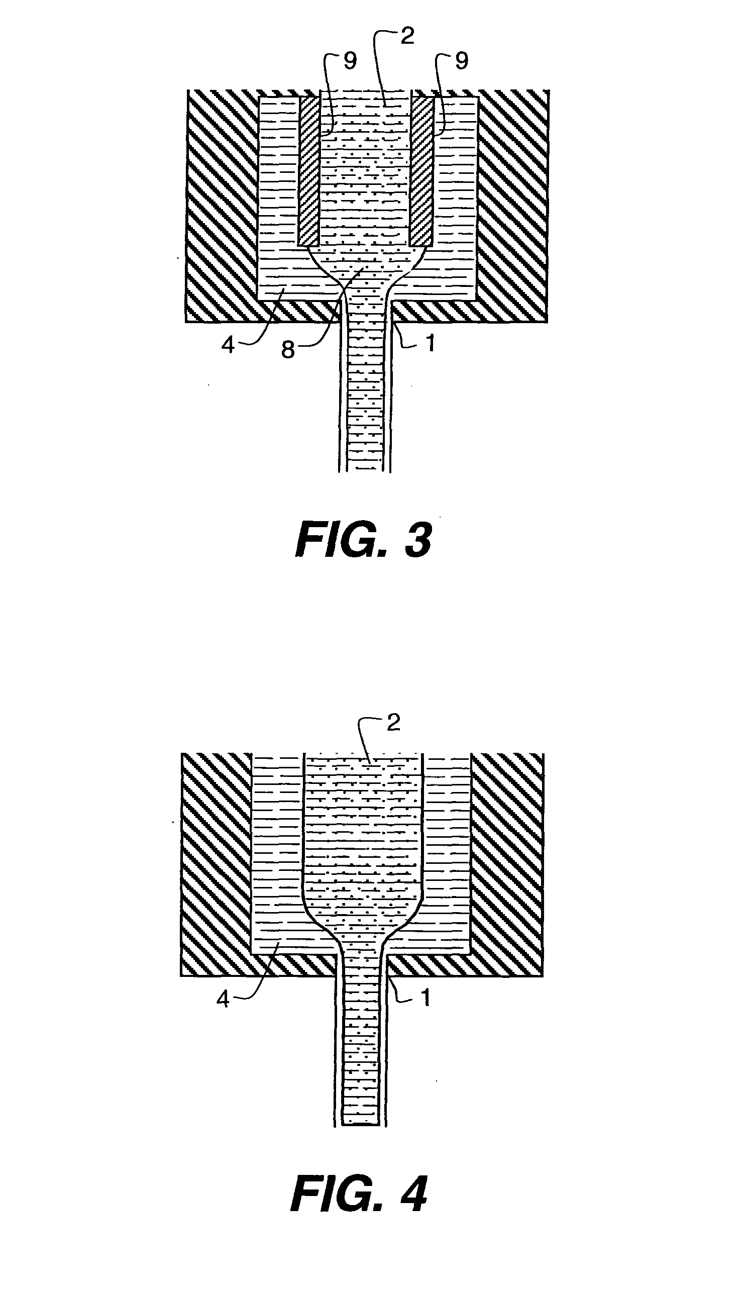
[0026]By ensuring the dispersed components or particles cannot come into contact with the wall the possibility of wear is removed.
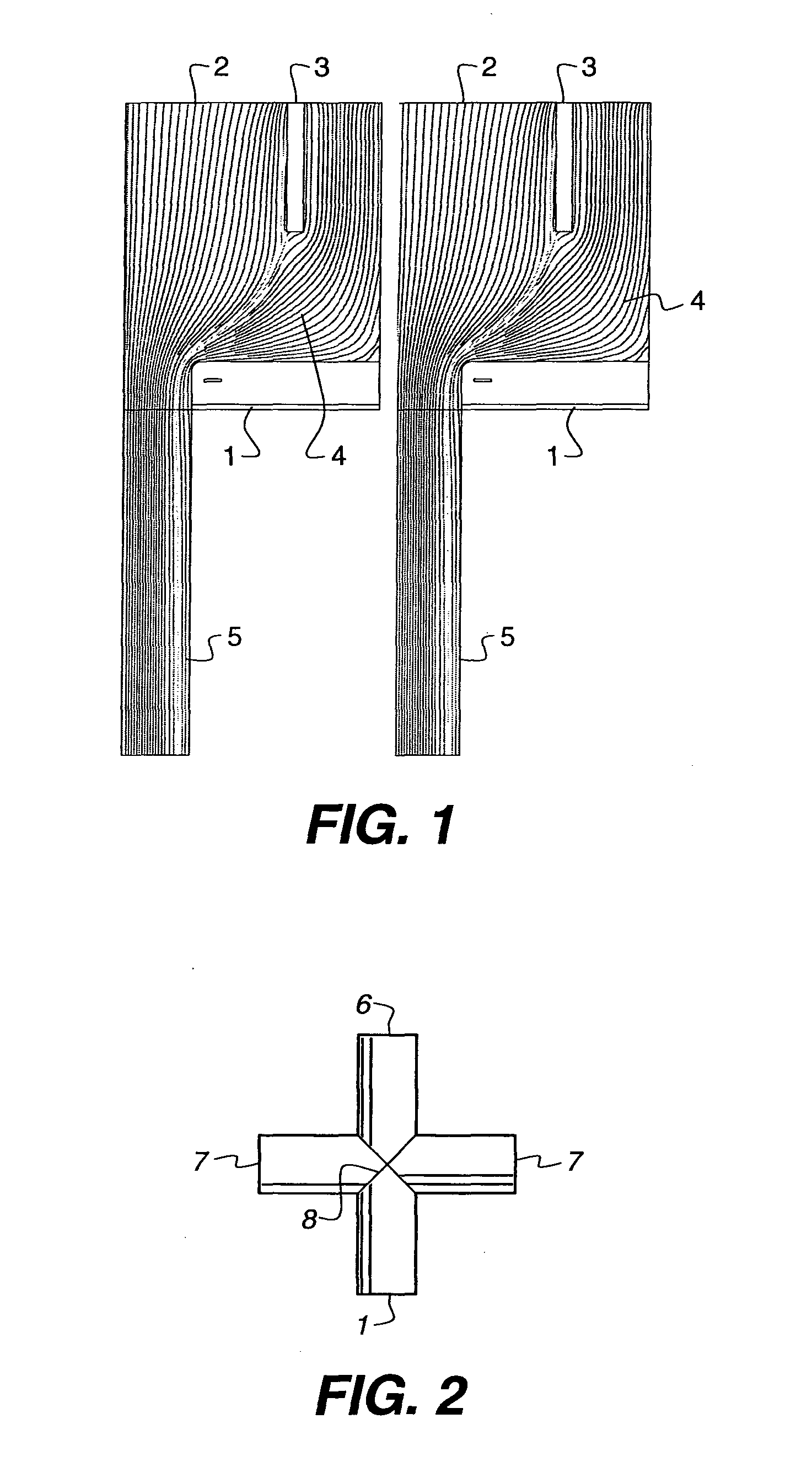
[0027]Since the fluidic system to separate the flows can be bigger than the nozzle, the issues of particles or components blocking the nozzle are ameliorated. Since particles are kept away from the nozzle wall there is no hard surface to jam against.
[0028]Furthermore by ensuring the dispersed material is kept away from the walls, and therefore from the thermal boundary layer, there is a significantly reduced thermal degradation effect on the dispersed material. Further, there is less possibility of material adhering to the walls.
[0029]As it is the interaction of dispersed material or particulates with the boundary layer within the nozzle that generates the observed drop velocity fluctuations, by keeping that material out of the nozzle boundary layer, the small drop merger length determined by the background fluid can be realised.
[0030]It is the viscosity of the liquid in the boundary layer that is responsible for the pressure drop required for a particular jetting velocity thus, for example, by addition of solvent as a thin layer surrounding a UV curable ink, the shear in the nozzle is only experienced by the solvent and thus the jettability of the higher viscosity material i.e. the UV curable monomer is improved. Additionally it may be advantageous to increase the overall temperature of the ink composition to reduce its viscosity.
[0031]Since the break up of the jet is driven by the liquid surface tension and initially the subsurface viscosity (of the jet), by keeping dispersed material away from this region, it is the properties of the background fluid that determine the drop break-up dynamics rather than the dispersed components. Thus the range of dispersed components that may be chosen is significantly broadened.

Problems solved by technology

This generates several issues that require resolution.
Further, for industrial printing technologies, i.e. employing printing as a means of manufacture, the liquid formulation may contain solid or dispersed components that are inherently difficult to handle with inkjet processes.
In this method the liquids are supplied by coaxially arranged nozzles, which are difficult to manufacture as an array.

Method used


Image

  • Method of continuous inkjet printing
  • Method of continuous inkjet printing
  • Method of continuous inkjet printing

Examples


Embodiment Construction

[0037]The invention relates to continuous ink jet printing rather than to drop on demand printing. Continuous ink jet printing uses a pressurized liquid source to feed a nozzle, which thereby produces a liquid jet. Such a liquid jet is intrinsically unstable and will naturally break to form a continuous stream of droplets. A perturbation to the jet at or close to the Rayleigh frequency, i.e. the natural frequency of break-up, will cause the jet to break regularly. The droplets of liquid or ink may then be directed as appropriate. The perturbation may be caused by, for example, one or more of a piezo element, a resistive heater element, an electro osmotic arrangement, an electrophoretic arrangement, or a dielectrophoretic arrangement. A continuous heater may additionally be provided to change the average temperature of the print head and thus modify the ink properties.

[0038]The liquid composition or ink may contain one or more dispersed or dissolved components including pigments, dye...


PUM


Abstract

A liquid jet is ejected out of a nozzle, the liquid comprising one or more components, the flow of one or more of said components, the active components, being separated such that the liquid that flows within a boundary layer thickness δ, of the nozzle wall is substantially comprised of a liquid without the active components, the continuous phase, and the said active components flow substantially outside said boundary layer where δ is defined by formula (I): where μ is the continuous phase viscosity in Pa·s, U is the jet velocity in m / s ρ is the continuous phase density in kg / m3 and x is the length of the nozzle in m in the direction of flow.δ=μxρU(I)

Description

FIELD OF THE INVENTION[0001]This invention relates to the field of continuous ink jet printing, especially in relation to inks or other jettable compositions containing dispersed components.BACKGROUND OF THE INVENTION[0002]With consumer printer market growth, inkjet printing has become a broadly applicable technology for supplying small quantities of liquid to a surface in an image-wise way. Both drop-on-demand and continuous drop devices have been conceived and built. Whilst the primary development of inkjet printing has been for graphics using aqueous based systems with some applications of solvent based systems, the underlying technology is being applied much more broadly.[0003]There is a general trend of formulation of inkjet inks toward pigment based ink. This generates several issues that require resolution. Further, for industrial printing technologies, i.e. employing printing as a means of manufacture, the liquid formulation may contain solid or dispersed components that are...

Claims


Application Information

Patent Timeline
IPC IPC(8): B41J2/14G01F11/00
CPCB41J2/03
Inventor CLARKE, ANDREW
Owner EASTMAN KODAK CO
Learn More